High-temperature pressure sensor and manufacturing method thereof

A pressure sensor, high temperature technology, applied in the direction of measuring fluid pressure, fluid pressure measurement by changing ohmic resistance, instruments, etc., can solve the problems of low shear strength, mismatch of high temperature thermal expansion coefficient, long-term and reliable work, etc. To achieve the effect of buffering thermal stress and compensating zero temperature drift

Inactive Publication Date: 2015-11-18
昆山泰莱宏成传感技术有限公司
View PDF6 Cites 10 Cited by
  • Summary
  • Abstract
  • Description
  • Claims
  • Application Information

AI Technical Summary

Problems solved by technology

In 2001, Xidian University made a high-temperature pressure sensor by epitaxial 3C-SIC film on a silicon base. Since the silicon carbide sensitive resistor is epitaxially formed on a silicon base that doubles as an elastic diaphragm, the operating temperature can only reach 200°C. , and because the above design does not use complete SiC materials, there is a problem of mismatching high-temperature thermal expansion coefficients between Si and 3C-SiC, which is likely to cause noise and increase the possibility of failure
In 2011, Tsinghua University did a certain degree of research on silicon carbide piezoresistive sensor chip technology, which did not involve the packaging structure research, and the performance of the sensor could not be measured without making a complete pressure sensor
In 2013, Xiamen University published the research results of silicon carbide capacitive pressure sensitive components, which adopted a more non-vacuum bonding technology. Since the metallized electrodes on the sensitive resistors were not protected against oxidation in vacuum, they could not work reliably for a long time. Moreover, it is limited to the research of sensitive components, without involving the more difficult signal extraction and packaging, and the performance of the sensor cannot be measured without making a complete pressure sensor
And because the structure is in the form of a flat diaphragm, the silicon dioxide membrane is mainly subjected to shear force, and the shear strength is much smaller than the compressive strength, which severely restricts the upper limit of the service temperature and cannot exceed 800 °C
Due to the flat diaphragm, the reflective layer opposite to the optical fiber is located in the center of the diaphragm, which will form a curved surface under pressure, which not only reduces the reflection efficiency, but also forms a certain range of dispersion in the reflection distance, especially when the center of the diaphragm and the center of the optical fiber are due to assembly errors. When it is not concentric, the measurement error will be greater

Method used


Image

  • High-temperature pressure sensor and manufacturing method thereof
  • High-temperature pressure sensor and manufacturing method thereof

Examples


Embodiment 1

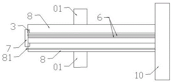
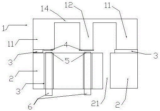
[0025] Such as figure 1 As shown, the sapphire single wafer (or zirconia, silicon carbide, alumina ceramics) is ground and processed into an integrated elastic element 1 having a fixed side 11, an elastic diaphragm 14 and a central column 12, namely an E-shaped cup, a reflective film, 4 and semi-permeable membrane 5 are metal oxides or nitrides formed by sputtering or reactive sputtering process, another sapphire single wafer (or zirconia, silicon carbide, alumina ceramic) as the base 2, two sapphire fibers 6 Pass through the hole and fix it on the base 2 with a high-temperature sintered layer 3 with aluminum oxide nanopowder as the main component. There is also a vent 21 on the base 2. The base 2 and the integrated elastic element 1 The fixed support 3 is composed of a high-temperature sintered layer 3 with aluminum oxide nanopowder as the main component to form a pressure-sensitive core 7 together.

[0026] Such as figure 2 As shown, the pressure-sensitive core 7 uses a high-...

Embodiment 2

[0028] The manufacturing method of a high temperature pressure sensor is as follows:

[0029] First, use a tubular grinding head with a gap at the end and an abrasive with a Mohs hardness greater than 9 on the drill press to grind annular grooves on a double-sided polished sapphire single crystal (or zirconia, alumina ceramic) sheet to make The integrated elastic element 1 of the fixed supporting edge 11, the elastic diaphragm 14 and the central hard core 12;

[0030] Second, use a sputtering process to form a metal oxide or nitride film on the end surface of the central hard core as the reflective film 4;

[0031] Third, use aluminum oxide powder (particle size less than 0.5 microns) as the main raw material, supplemented by solvents, resins, plasticizers, dispersants and other organic additives to make slurry. The slurry is coated on the corresponding area of ​​the base 2 and the fixed side 11 with a screen printer, and the slurry is dried and degummed. The sapphire optical fiber...


PUM

PropertyMeasurementUnit
particle diameteraaaaaaaaaa

Abstract

The invention discloses a high-temperature pressure sensor, which comprises a pressure sensitive core body, a high-temperature sintering layer and a connecting rod, wherein the pressure sensitive core body is connected with the connecting rod through the high-temperature sintering layer, the head part of the connecting rod is provided with a platinum-rhodium platinum thermocouple for measuring temperature and compensating thermal sensitivity drift and thermal zero drift, the middle part of the connecting rod is connected with a high-temperature alloy steel fixing member in clamping and sleeving manner, the high-temperature alloy steel fixing member is connected with a measured structure, the tail part of the connecting rod is provided with a signal processing circuit, a sapphire optical fiber is installed in the interior of the connecting rod, and the pressure sensitive core body is connected with the signal processing circuit through the sapphire optical fiber. The purpose of the invention is to provide the high-temperature pressure sensor which can measure gas pressure at 1200 DEG C ambient temperature, directly measure intensity of pressure of the high-temperature gas ejected by a jet engine of an aircraft or a rocket without using a pressure guiding pipe, and measures the thrust of the jet engine in real time.

Description

Technical field [0001] The invention relates to a high temperature pressure sensor and a manufacturing method thereof. Background technique [0002] The traditional pressure sensor is mainly a mechanical structure type device, and the deformation of an elastic element is used to indicate the pressure. This structure is large in size and heavy in mass, and cannot provide electrical output. With the development of semiconductor technology and MEMS technology, people have developed silicon micro pressure sensors using silicon as the main material, using various forms such as capacitance and piezoresistance, which are characterized by small size, light weight, high accuracy, and good temperature characteristics. . [0003] With the expansion of applications and research, people began to pay more attention to the development of micro pressure sensors that can directly work in harsh environments. The so-called "harsh environment" refers to environments with high temperature, strong rad...

Claims


Application Information

Patent Timeline
Patent Type & Authority Applications(China)
IPC IPC(8): G01L19/04G01L9/06
Inventor 杨银堂李策李跃进
Owner 昆山泰莱宏成传感技术有限公司
Why Eureka
Try Eureka