Discrete gas film cooling hole structure

A technology of air film cooling and pore structure, which is applied in the direction of blade support components, engine components, machines/engines, etc., can solve problems such as uneven air film coverage, achieve uniform air film flow and coverage, and reduce aerodynamic mixing loss , The effect of large air film coverage area

Active Publication Date: 2017-02-22
INST OF ENGINEERING THERMOPHYSICS - CHINESE ACAD OF SCI
View PDF3 Cites 14 Cited by
  • Summary
  • Abstract
  • Description
  • Claims
  • Application Information

AI Technical Summary

Problems solved by technology

However, the rectangular cross-section gas film hole has side wall effect, that is, the side wall causes non-uniform gas film coverage

Method used


Image

  • Discrete gas film cooling hole structure
  • Discrete gas film cooling hole structure
  • Discrete gas film cooling hole structure

Examples


Embodiment Construction

[0034] In order to make the object, technical solution and advantages of the present invention clearer, the present invention will be further described in detail below in conjunction with specific embodiments and with reference to the accompanying drawings.

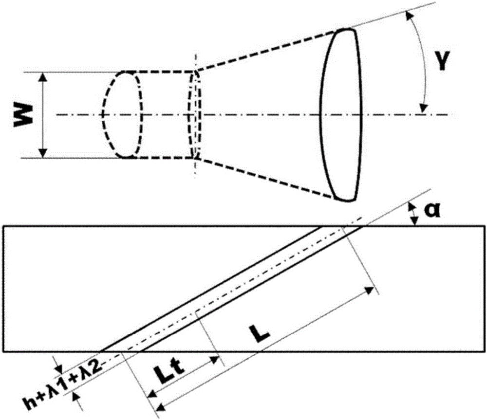
[0035] Figure 1a It is a structural schematic diagram of the cooling hole of the present invention. The cooling holes provided by the present invention for air film cooling of the gas turbine blade body or the upper and lower end walls of the blade channel are divided into two parts: a straight section and an expanded section along the cold air flow direction. The straight section is located at the cold air inlet side, and the expanded section is located at the On the cold air outlet side, the length of the straight section of the hole is represented by Lt, the total length of the hole is represented by L, and the ratio Lt / L of the length of the straight section to the total length of the cooling hole is between 1 / 4 and 1...


PUM


Abstract

The invention discloses a discrete gas film cooling hole structure, and relates to gas turbine cooling technologies. Hole patterns are formed with shuttle-like cross sections. Each whole hole is expanded and composed of two sections, the straight section is located on the cooling gas side, and the expanded section is located on the high-temperature gas side. The cross section of each straight section is in a shuttle shape, the shuttle shape is composed of four arc sections which are tangential, and the upstream walls and the downstream walls protrude outwards; and the arcs on the two sides of each straight section expand transversely to form the two side faces of the corresponding expanded section, and the upstream walls and the downstream walls of the expanded sections are outwards-protruding hook faces. The whole gas film cooling hole structure is high in cooling effect, and the gas film cover area is large; controllable inverted-kidney-shaped vortex pairs are generated on the downstream portion, and transverses gas film covering is uniform; speed at a cooling gas outlet is high, and the pneumatic mixing loss is small; and machining is easy, and the structure can be realized through existing gas film hole machining technologies. The gas film hole patterns are used for cooling gas turbine blades and are suitable for pressure surfaces, suction surfaces, upper end wall surfaces and lower end wall surfaces of the turbine blades.

Description

technical field [0001] The invention relates to the field of gas turbine cooling technology, in particular to a discrete film cooling hole structure. Background technique [0002] Gas turbines are widely used in aviation, military, transportation, electric power and other fields. The pursuit of higher efficiency is an important goal of gas turbine development. Increasing the inlet temperature of the turbine is the most effective way to improve the efficiency of the gas turbine. At present, the turbine inlet temperature of heavy-duty gas turbines and high-thrust aero-engines on the ground has far exceeded the temperature resistance limit of turbine blade alloy materials. Turbine cooling technology must be used to ensure long-term reliable operation of turbine blades. Discrete hole film cooling is an efficient cooling technology commonly used in gas turbine blades at present. Its basic principle is to introduce cooling air from the compressor to the inner cavity of the turbine...

Claims


Application Information

Patent Timeline
Patent Type & Authority Applications(China)
IPC IPC(8): F01D5/18
CPCF01D5/186F05D2220/32F05D2260/202
Inventor 安柏涛刘建军
Owner INST OF ENGINEERING THERMOPHYSICS - CHINESE ACAD OF SCI
Why Eureka
Try Eureka