Igniting device and ignition method for sintering

The technology of an ignition device and an ignition furnace is applied in the direction of combustion ignition, a combustion method, and an igniter equipped with fuel, etc., which can solve the problems of cumbersome switching between burners and spare burners, short distance of flame elongation, and poor quality of sintered minerals. To improve the quality of sintered ore, reduce consumption, and avoid insufficient heat supply

Active Publication Date: 2017-02-22
MAANSHAN IRON & STEEL CO LTD
View PDF9 Cites 9 Cited by
  • Summary
  • Abstract
  • Description
  • Claims
  • Application Information

AI Technical Summary

Problems solved by technology

However, the spare burner has been baked at high temperature in the furnace for a long time, which is very easy to damage, and the conversion and use of the normal burner and the spare burner is relatively cumbersome
Patent No. "ZL892092181" discloses a curtain-type igniter, the flame length can be adjusted by the ratio of the primary and secondary air volume, the adjustment of the flame length is a common practice in the sintering ignition furnace industry, but practice has proved that the flame can elongate the distance Short and high gas consumption
[0005] To sum up, although the current sinter ignition devices have various types and different designs, they generally have the disadvantages of low ignition quality, which in turn leads to high energy consumption for sintering and limited quality of sintered ore. How to effectively improve the quality of sintered ore and reasonably Reducing its energy consumption has become the main direction of development in the industry

Method used


Image

  • Igniting device and ignition method for sintering
  • Igniting device and ignition method for sintering
  • Igniting device and ignition method for sintering

Examples


Embodiment 1

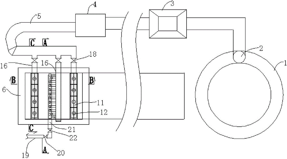
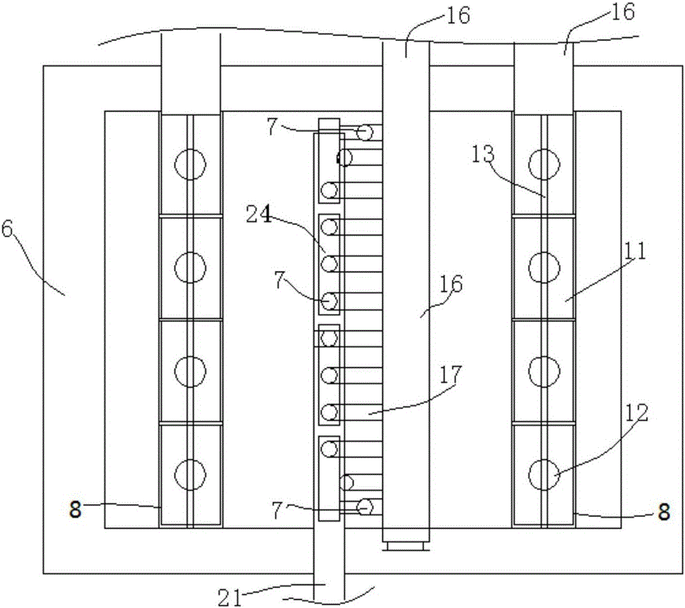
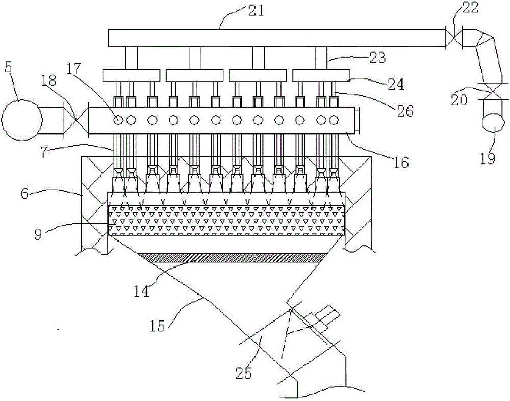
[0042] Such as figure 1 , figure 2 , image 3 , Figure 4 , Figure 5 , Image 6 As shown, a kind of sintering ignition device of the present embodiment comprises an ignition furnace 6, a gas inlet pipe and a hot air inlet pipe, and the ignition furnace 6 includes an ignition section and a heat preservation section, wherein the front and rear end furnace tops of the ignition section are respectively provided with An isolation chamber 8, which communicates with the hot air intake pipe. A row of burners 7 are vertically arranged on the top of the ignition furnace 6 ignition section, such as figure 2 As shown, there are 12 burners in total, the eight burners 7 in the middle are arranged in a straight line and evenly spaced, the last two burners 7 near the sides of the sintering machine trolley are arranged in an arc, and the burners 7 The height from the surface of the sintered material 9 is 10-20 mm lower than that of the middle burner 7 , specifically, in this embodimen...

Embodiment 2

[0055] Such as figure 1 , figure 2 , image 3 , Figure 4 , Figure 5 , Image 6 As shown, a sintering ignition device of this embodiment has the same basic structure as that of Embodiment 1, the difference is that the length of the ignition furnace 6 in this embodiment accounts for 14% to 20% of the length of the sintering machine body, and the ignition section furnace The height from the top to the surface of the sintered material 9 is 800-900mm, and the distances between the front and rear isolation chambers 8 and the central burner 7 are 800-1000mm and 1300-1500mm respectively.

[0056] Isolation chamber 8 among the present embodiment comprises the ventilation hole 12 that is connected with hot blast branch pipe 16, and this ventilation hole 12 extends to the stove top inner wall of ignition furnace 6, and the bottom of ventilation hole 12 is provided with buffer chamber 11, and the buffer chamber 11 The bottom is provided with a strip-shaped nozzle 13, which forms a...

Embodiment 3

[0069] Such as figure 1 , figure 2 , image 3 , Figure 4 , Figure 5 , Image 6 As shown, a kind of sintering ignition device of this embodiment has the same basic structure as that of Embodiment 2, the difference is that the height of the arc-shaped burners 7 in this embodiment from the surface of the sintered material 9 is lower than that of the middle burner 7 20mm; the gas outlet end of the burner 7 is embedded in the insulation layer, and the embedding depth is 25mm; the cross-sectional area of ​​the bellows 15 at the installation position of the baffle 14 is S, and the upper surface area of ​​the baffle 14 is 60% S, That is, the wind blocking area of ​​the spoiler 14 accounts for 60% of the ventilation area of ​​the bellows 15; the isolation chamber 8 is made of heat-resistant stainless steel.


PUM


Abstract

The invention discloses an igniting device and an ignition method for sintering and belongs to the field of iron smelting of a blast furnace. The igniting device disclosed by the invention comprises an ignition furnace, a gas charging pipe and a hot air charging pipe; a row of burner nozzles are arranged on a part, at an ignition section of the ignition furnace, of the furnace top; the middle burner nozzles are arranged linearly; the burner nozzles close to the two sides of a sintering machine trolley are arranged in an arc shape; each burner nozzle communicates with the gas charging pipe and the hot air charging pipe respectively; the parts, at the front end and the rear end of the ignition section, of the furnace top are each provided with an isolation chamber; each isolation chamber communicates with the hot air charging pipe; an air box is arranged at the bottom of the ignition furnace, wherein a retarder is arranged inside the air tank under the burner nozzles. The igniting device disclosed by the invention has the advantages of optimizing distribution of an igniting fuel on an overall sintering material surface, balancing the ignition quality of sintering materials at all positions of a sintering machine, improving the quality of sintered ore products, also enhancing the ignition effect, reducing consumption of the igniting fuel and satisfying the production process requirements on energy conservation and environmental protection.

Description

technical field [0001] The invention relates to the technical field of blast furnace ironmaking, and more specifically relates to a sintering ignition device and an ignition method. Background technique [0002] The sintering process is a major energy consumer in steel production, mainly including solid fuel consumption, gas consumption, and electricity consumption, of which solid fuel consumption accounts for about 75%, electricity consumption accounts for about 15%, and gas consumption accounts for about 6%. In the sintering process, the purpose of ignition is to provide enough heat on the surface of the mixture to ignite and burn the solid fuel in it, and at the same time make the surface mixture dry, decarburize and sinter under the action of high-temperature flue gas in the igniter, and with the help of The draft makes the sintering process continue from top to bottom. [0003] The structure and form of the ignition device have a great influence on the quality of the i...

Claims


Application Information

Patent Timeline
Patent Type & Authority Applications(China)
IPC IPC(8): F27B21/08F23D14/48F23Q2/16F27D13/00
CPCF23D14/48F23Q2/16F27B21/00F27D13/00
Inventor 张永中张晓萍曹建民刘自民李顺祥周宗林
Owner MAANSHAN IRON & STEEL CO LTD
Why Eureka
Try Eureka