Trapezoidal tilted baffle plate shell and tube type heat exchanger

A technology of shell-and-tube heat exchangers and baffles, which is applied to the types of heat exchangers, heat exchanger shells, indirect heat exchangers, etc., and can solve the problem of difficult production and complicated processing technology of continuous spiral baffle heat exchangers and other problems, to achieve the effect of reducing the pressure drop on the shell side, improving the heat transfer coefficient and comprehensive performance, and overcoming difficult processing

Active Publication Date: 2017-02-22
ZHENGZHOU UNIV
View PDF9 Cites 3 Cited by
  • Summary
  • Abstract
  • Description
  • Claims
  • Application Information

AI Technical Summary

Problems solved by technology

However, the processing technology of the continuous spiral baffle heat exchanger is relatively complicated, and it is not easy to produce

Method used


Image

  • Trapezoidal tilted baffle plate shell and tube type heat exchanger
  • Trapezoidal tilted baffle plate shell and tube type heat exchanger
  • Trapezoidal tilted baffle plate shell and tube type heat exchanger

Examples


Embodiment 1

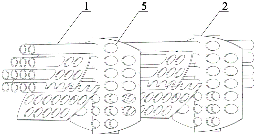
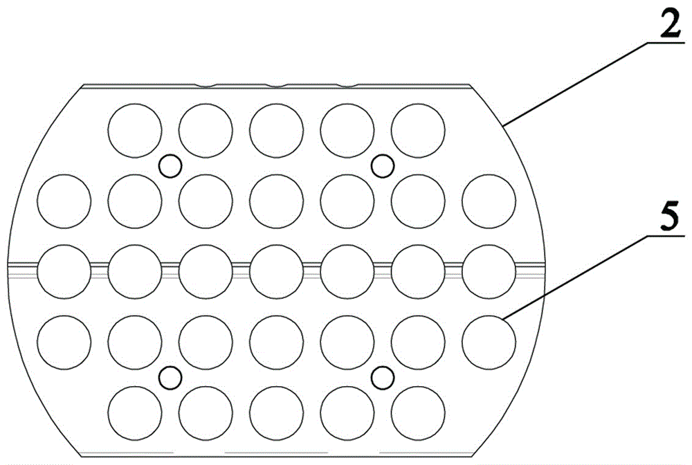
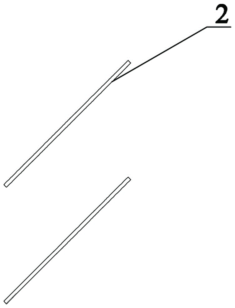
[0029] This embodiment provides a trapezoidal inclined baffle shell-and-tube heat exchanger, including a shell, a heat exchange tube 1, a tube sheet, tie rods and a trapezoidal baffle 2, such as Figure 1~5 As shown, two adjacent sets of trapezoidal baffles 2 are arranged orthogonally, and two sets of trapezoidal baffles 2 are arranged in parallel, each group includes two parallel trapezoidal baffles 2, and the trapezoidal baffles The flow plate 2 corresponds to the heat exchange tube 1 with several holes 5 evenly distributed, the heat exchange tube 1 is arranged through the hole 5, the trapezoidal baffle 2 is arranged obliquely, and the trapezoidal baffle 2 and The included angle of the heat exchange tube 1 =45°, the schematic diagram of the flow state when the shell-side fluid flows through a set of trapezoidal baffles 2, such as Figure 9 As shown, after the shell-side fluid flows in one direction in one set of trapezoidal baffles 2, it flows in another direction after fl...

Embodiment 2

[0033] Such as Figure 7 As shown, the difference between this embodiment and Embodiment 1 is that two sets of alternate trapezoidal baffles 2 are arranged symmetrically;

Embodiment 3

[0035] Such as Figure 8 As shown, the difference between this embodiment and the above-mentioned embodiment is that each group includes three trapezoidal baffles 2, and the distance between the trapezoidal baffles 2 in each group is , the quasi-trapezoidal baffles 2 in the middle of each group are cut from the two ends of the long axis by elliptical plates, and the height is The bow-shaped plate is made; the quasi-trapezoidal baffle plate 2 in the middle of each group is cut from the two ends of the long axis of the elliptical plate with a height of He Gaowei made of a segmented plate, where R is the radius of the shell and the major axis of the ellipse is , the minor axis is 2R.

[0036] In other embodiments, the difference from the above embodiments lies in: the included angle between the trapezoidal baffle plate 2 and the heat exchange tube 1 Can be set according to needs.


PUM


Abstract

The invention provides a trapezoidal tilted baffle plate shell and tube type heat exchanger. The exchanger comprises a shell body, heat exchange tubes, tube sheets, pull rods and trapezoidal baffle plates. Two groups of adjacent trapezoidal baffle plates are in perpendicular arrangement. Each group of trapezoidal baffle plates includes at least tow parallel trapezoidal baffle plates. The trapezoidal baffle plate is provided with a plurality of evenly distributed holes for mounting the heat exchange tubes correspondingly, which pass through the holes. The trapezoidal baffle plates are placed in a tilted mode. The rims of the trapezoidal baffle plates are provided with evenly distributed tube fixing holes for mounting the pull rods correspondingly which pass through the tube fixing holes. The pull rods are covered by the tube distance fixers in a sleeve mode. The tube distance fixers are fixed to the pull rods by bolts. The heat exchanger has the advantage of being able to effectively enhance the heat exchanging efficiency, being easily processed, and having broad application prospect.

Description

technical field [0001] The invention relates to the field of heat exchangers, in particular to a trapezoidal inclined baffle shell-and-tube heat exchanger. Background technique [0002] With the rapid development of economy and industry, countries all over the world are facing the problem of energy shortage, so how to efficiently use existing energy is the focus of people's increasing attention. Among them, the heat exchanger can not only reasonably adjust the temperature of the process medium to meet the needs of the process, but also an effective device for waste heat and waste heat recovery and utilization. At present, the most widely used heat exchanger is the shell and tube heat exchanger. However, due to structural reasons, there is a large flow dead zone and pressure drop along the shell side. [0003] In order to solve the above problems, in recent years, some new shell-and-tube heat exchangers using spiral baffles have been developed in the industry. The disadvan...

Claims


Application Information

Patent Timeline
Patent Type & Authority Applications(China)
IPC IPC(8): F28D7/16F28F9/24
CPCF28D7/1607F28F9/24
Inventor 古新罗元坤熊晓朝王永庆秦晓柯
Owner ZHENGZHOU UNIV
Why Eureka
Try Eureka