Unmanned aerial vehicle tunnel inspection system based on BIM technology

A patrol inspection system and unmanned aerial vehicle technology, applied in the direction of navigation through speed/acceleration measurement, can solve the problem of low navigation accuracy, achieve the effect of fast data collection, rich information, and reduced inspection time

Active Publication Date: 2017-02-22
SHANGHAI UNIV
View PDF6 Cites 29 Cited by
  • Summary
  • Abstract
  • Description
  • Claims
  • Application Information

AI Technical Summary

Problems solved by technology

[0003] From the patents searched at home and abroad, there is no patent on the application of drones to tunnel inspection lines. This is because there are many lines in the tunnel, and no matter how precisely the drone is controlled in the tunnel, it will touch the tunnel. The probability of the situation in the inner line occurs; on the other hand, the accuracy of indoor navigation is low due to the lack of GPS in the past

Method used


Image

  • Unmanned aerial vehicle tunnel inspection system based on BIM technology
  • Unmanned aerial vehicle tunnel inspection system based on BIM technology
  • Unmanned aerial vehicle tunnel inspection system based on BIM technology

Examples


Embodiment 1

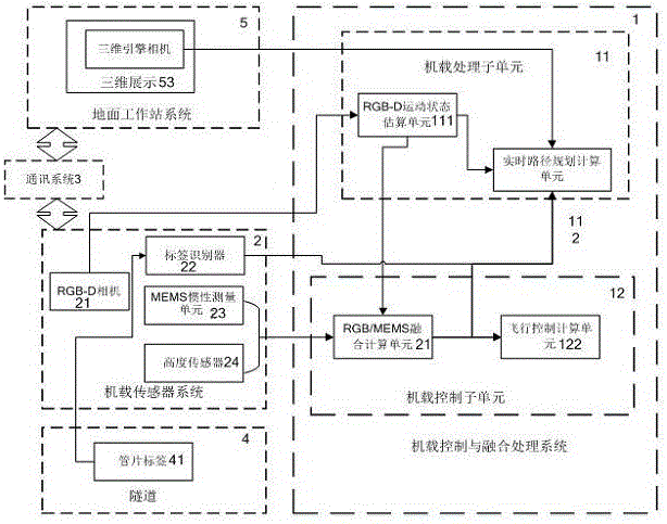
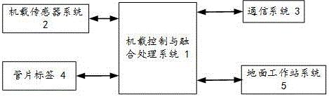
[0056] See Figure 1 ~ Figure 5 , The UAV tunnel inspection system based on BIM technology is characterized in that the airborne control and fusion processing system is connected to the segment label, airborne sensor, communication system and ground workstation system;

[0057] 1) The segment label is used to locate the position of the segment in the tunnel;

[0058] 2) Ground workstation system, used to control and navigate the UAV's inspection route in the tunnel; among them, the control and navigation of the inspection route further include:

[0059] The correspondence establishment subunit is used to obtain the correspondence between the drone and the 3D engine roaming camera in the 3D display of the tunnel model based on BIM technology;

[0060] The 3D model generation subunit of the inspection route is used to obtain the real 3D model of the UAV in the tunnel inspection route;

[0061] 3) The airborne sensor system is used to obtain images of tunnel diseases in the tunnel inspect...

Embodiment 2

[0071] See figure 1 , Reveals a UAV tunnel inspection system based on BIM technology, including: an airborne control and fusion processing system connected to the segment label, ground workstation system, airborne sensor system and communication system.

[0072] See Figure 4 The ground workstation system of this embodiment includes a correspondence establishment subunit and a three-dimensional model production subunit of the inspection route; the correspondence establishment subunit is used to establish a tunnel model through BIM technology and import it into the three-dimensional display software. The coordinate system conversion method obtains the relationship between the drone navigation coordinate system and the coordinate system of the 3D engine roaming camera, and establishes the corresponding relationship between the drone and the 3D engine roaming camera; firstly, obtain the drone leaving the tunnel through the RGB-D camera For the left, right and upper distances, adjust...

Embodiment 3

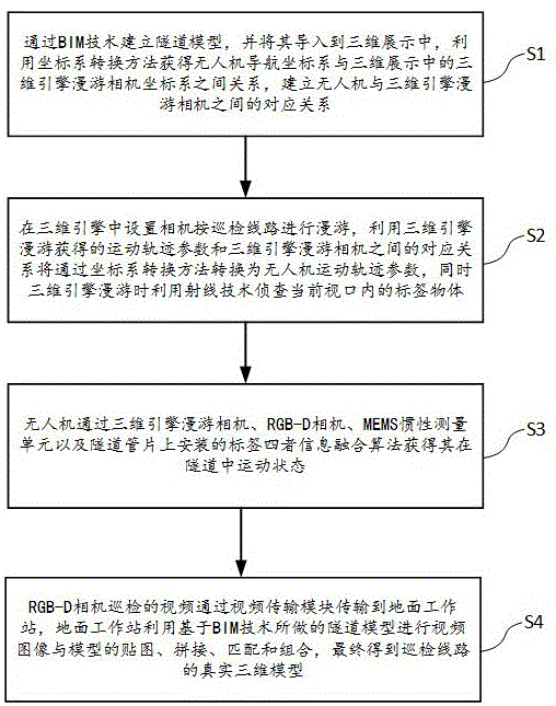
[0112] See image 3 , This BIM technology-based drone tunnel inspection method includes the following steps:

[0113] [Step 1] Establish the tunnel model through BIM technology and import it into the 3D display, use the coordinate system conversion method to obtain the relationship between the drone navigation coordinate system and the 3D engine roaming camera coordinate system, and establish the drone and 3D engine Correspondence between roaming cameras;

[0114] Among them, the coordinate system conversion method obtains the relationship between the drone navigation coordinate system and the three-dimensional engine roaming camera coordinate system. The relationship is obtained by first obtaining the distance between the drone and the tunnel from the left, right, and up through the RGB-D camera, adjusting the drone to the same position as the starting coordinates of the 3D engine roaming, so that the two coordinate systems coincide, and then using The quaternion performs the coo...


PUM


Abstract

The invention relates to an unmanned aerial vehicle tunnel inspection system based on BIM technology. The system comprises a correspondence establishment module, an attitude/position information acquisition module and a motion state acquisition module, wherein the correspondence establishment module obtains the relationship between an unmanned aerial vehicle navigation coordinate system and a three-dimensional engine roaming camera coordinate system; the attitude/position information acquisition module sets a camera to roam along an inspection line in a three-dimensional engine, converts the obtained correspondence between the motion trail parameter and the three-dimensional engine roaming camera into an unmanned aerial vehicle motion trail parameter, and obtains a pose parameter in the unmanned aerial vehicle inspection line; and the motion state acquisition module acquires the information corresponding to the mounting labels on the three-dimensional engine roaming camera, the RGB-D based camera, an MEMS inertial measurement unit and a tunnel segment, and integrates the information of the four to obtain the motion state in the tunnel. The system provided by the invention can improve the working efficiency of tunnel inspection.

Description

Technical field [0001] The invention belongs to the technical field of tunnel inspection, and relates to a tunnel inspection system, in particular to a UAV tunnel inspection system based on BIM technology. Background technique [0002] The methods commonly used in tunnel inspection at home and abroad mainly include manual inspection and semi-automatic instrument inspection. Among them, manual detection can only have two or three hours of detection time due to the daily operation of the tunnel, which leads to short manual detection lines. Semi-automated instrument detection requires embedded detection sensors during tunnel production, and special communication equipment is installed during tunnel operation. Moreover, the survival rate of embedded sensors is not very high, which leads to current tunnel inspections. It is still carried out mainly by manual inspection. [0003] Judging from the patents searched at home and abroad, there is currently no patent for applying drones to t...

Claims


Application Information

Patent Timeline
Patent Type & Authority Applications(China)
IPC IPC(8): G01C21/16
CPCG01C21/16
Inventor 高新闻简明胡珉林欣欣周显威
Owner SHANGHAI UNIV
Why Eureka
Try Eureka