Solar cell module with high photoelectric conversion efficiency

A technology of photoelectric conversion efficiency and solar cells, which is applied in the field of solar energy, can solve the problems of cumbersome inversion of series connection and reduce photoelectric conversion efficiency, etc., and achieve the effect of series connection

Inactive Publication Date: 2017-02-22
广东永明建设发展有限公司
View PDF8 Cites 2 Cited by
  • Summary
  • Abstract
  • Description
  • Claims
  • Application Information

AI Technical Summary

Problems solved by technology

[0003] The purpose of the present invention is to provide a solar cell module with high photoelectric conversion efficiency, so as to improve the probl...

Method used


Image

  • Solar cell module with high photoelectric conversion efficiency
  • Solar cell module with high photoelectric conversion efficiency
  • Solar cell module with high photoelectric conversion efficiency

Examples


Embodiment 1

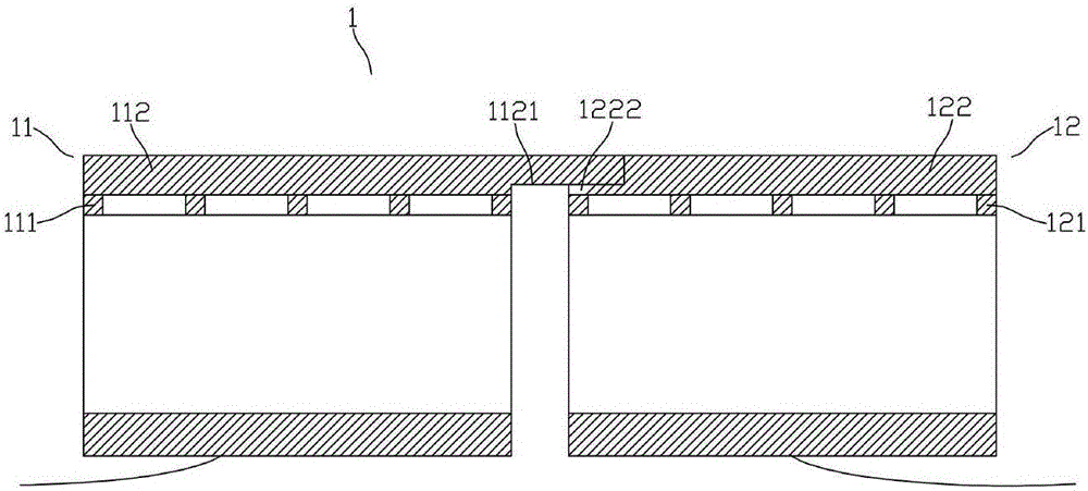
[0030] See figure 1 As shown, the solar cell panel 1 includes a first-type solar cell 11 and a second-type solar cell 12 , the front electrode 111 of the light-receiving surface of the first-type solar cell 11 is an n-type electrode, and the second-type solar cell 12 light-receiving surface front electrode 121 is a p-type electrode, a bus bar electrode 112 is formed on the front electrode of the first type solar cell, a bus bar electrode 122 is formed on the front electrode of the second type solar cell, and a first electrode is formed on one side of the bus bar electrode 112 of the first type solar cell 11 The finger structure 1121, the first electrode of the first type solar cell 11 The finger structure 1121 has a finger thickness smaller than the thickness of the bus bar electrode 112 of the first type solar cell 11, and the side of the second type solar cell 12 close to the first type solar cell 11 is busted The strip electrodes 122 form a second electrode groove 1222 stru...

Embodiment 2

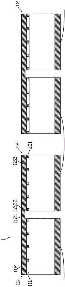
[0032] See figure 2 and image 3As shown, the solar panel 1 includes two first-type solar cells 11 and two second-type solar cells 12 formed side by side, the first-type solar cells 11 and the second-type solar cells 12 are staggered, and the first-type solar cells 11 are arranged side by side. The front electrode 111 of the light-receiving surface is an n-type electrode, the front electrode 121 of the light-receiving surface of the second type of solar cell 12 is a p-type electrode, the bus bar electrode 112 is formed on the front electrode of the first type of solar cell, and the bus bar is formed on the front electrode of the second type of solar cell. The bar electrode 122, the first electrode finger structure 1121 is formed on one side of the bus bar electrode 112 of the first type solar cell 11, and the finger thickness of the first electrode finger structure 1121 of the first type solar cell 11 is smaller than that of the bus bar electrode 112 of the first type solar c...

Embodiment 3

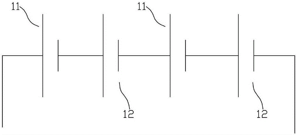
[0034] See Figure 4 As shown, the solar panel 1 includes two first-type solar cells 11 and one second-type solar cell 12 formed side by side, the first-type solar cells 11 and the second-type solar cells 12 are staggered, and the first-type solar cells 11 receive light The front surface electrode 111 is an n-type electrode, the front surface electrode 121 of the light-receiving surface of the second type solar cell 12 is a p-type electrode, a bus bar electrode 112 is formed on the front surface electrode of the first type solar cell, and a bus bar is formed on the front surface electrode of the second type solar cell. Electrode 122, first type solar cell 11 bus bar electrode 112 forms a first electrode finger structure 1121 on one side, and a first electrode groove structure 1122 on the opposite side, the first type solar cell 11 The first electrode finger structure 1121 has a finger thickness and a first The thickness of the electrode groove structure 1122 is smaller than th...


PUM


Abstract

The invention discloses a solar cell module with high photoelectric conversion efficiency. A solar cell panel comprises a first type of solar cell and a second type of solar cell, wherein the polarities of front electrodes of light receiving surfaces of the first type of solar cell and the second type of solar cell are opposite; a first electrode finger structure is formed at one side of the front electrode of the first type of solar cell, a second electrode groove structure is formed on the front electrode at one side, near the first type of solar cell, of the second type of solar cell, the first electrode finger structure is complementary with the second electrode groove structure, the finger length of the first electrode finger structure is greater than the groove length of the second electrode groove structure, and the first electrode finger structure of the first type of solar cell is electrically connected with the second electrode groove structure of the second type of solar cell. The solar cell module has the advantages that the problems of decreasing of photoelectric conversion efficiency and complicated serial turnover are solved when the conductive material is electrically connected with the solar cell, and the output power is flexibly improved.

Description

technical field [0001] The present invention relates to the technical field of solar energy, in particular to a solar cell module. Background technique [0002] Because of energy and environmental concerns, solar cells are of public concern. A solar cell is a power generation device that uses the photoelectric effect to obtain photoelectric power. In a solar cell, electrons and holes collected by the n-type electrode and the p-type electrode, respectively, are generated in the formation of a p-n junction semiconductor substrate. The solar cells are connected by interconnects to form a solar cell module. The solar cell module can increase the voltage by connecting the solar cells in series, and can also increase the current by connecting the solar cells in parallel, thereby increasing the output power of the solar cell module. In the prior art, different solar cells are usually electrically connected in parallel or in series through conductive materials. For solar cells who...

Claims


Application Information

Patent Timeline
IPC IPC(8): H01L31/02H01L31/042H01L31/05
CPCY02E10/50H01L31/0508H01L31/0201H01L31/042H01L31/0516
Inventor 李风浪李舒歆
Owner 广东永明建设发展有限公司
Why Eureka
Try Eureka