Hybrid magnetic circuit rotor of permanent magnet synchronous motor

A technology of permanent magnet synchronous motor and hybrid magnetic circuit, which is applied in the direction of magnetic circuit rotating parts, magnetic circuit, magnetic circuit shape/style/structure, etc. The effects of small magnetic coefficient, reduced magnetic flux leakage coefficient, and wide operating range of constant power

Inactive Publication Date: 2017-02-22
BEIJING INSTITUTE OF TECHNOLOGYGY
View PDF5 Cites 17 Cited by
  • Summary
  • Abstract
  • Description
  • Claims
  • Application Information

AI Technical Summary

Problems solved by technology

Although the traditional V-type built-in permanent magnet synchronous motor has a wide range of constant power operation, the motor has serious magnetic flux leakage, and because the magnetic isolation bridge is very thin, the mechanical reliability of the motor at high speed is reduced.

Method used


Image

  • Hybrid magnetic circuit rotor of permanent magnet synchronous motor
  • Hybrid magnetic circuit rotor of permanent magnet synchronous motor
  • Hybrid magnetic circuit rotor of permanent magnet synchronous motor

Examples


Embodiment 1

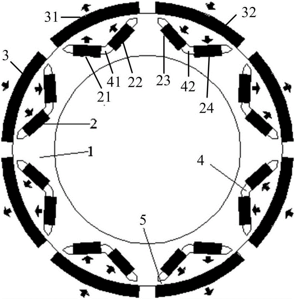
[0032] Embodiment 1: as figure 1 As shown, the hybrid magnetic circuit rotor of the present invention includes a rotor structural body 1 , a built-in permanent magnet 2 , a surface-mounted permanent magnet 3 and a magnetic isolation bridge 5 . A plurality of permanent magnet slots 4 are provided on the rotor structure body 1, and the magnetic isolation bridge 5 is arranged between the extension of the permanent magnet slot 4 and the outer edge of the rotor structural body 1, and the width of the magnetic isolation bridge 5 is 1-5 mm. , the thickness range is 0.5-3mm. The V-shaped permanent magnet slot 4 includes two inline embedded parts. The built-in permanent magnet 3 is embedded in the permanent magnet groove 4, and each inline embedded part is built with a built-in permanent magnet 2, and the built-in permanent magnet 2 is a rectangular permanent magnet, and the surface-mounted permanent magnet 3 is facing each permanent magnet. The magnet slots 4 are fixed on the outer ...


PUM


Abstract

The invention discloses a hybrid magnetic circuit rotor of a permanent magnet synchronous motor. The hybrid magnetic circuit rotor comprises a rotor structure body, a built-in permanent magnet and surface-mounted permanent magnets. The rotor structure body is provided with a plurality of permanent magnet grooves. The built-in permanent magnet is embedded in the permanent magnet grooves. Each surface-mounted permanent magnet is provided with a permanent magnet groove directly facing to the surface-mounted permanent magnet. The surface-mounted permanent magnet is fixed on the outer circumference face of the rotor structure body. One surface-mounted permanent magnet and the built-in permanent magnet in the permanent magnet grooves which directly faces to the surface-mounted permanent magnet form one magnetic pole. The polarities of the neighboring magnetic poles are opposite. The rectangular axis inductance difference of the hybrid magnetic circuit rotor generates the reluctance torque, and the constant power operation range of the motor is widened. The surface-mounted permanent magnet provides the magnetic circuit capable of hinging a stator winding to the original leakage magnetic flux, the magnetic flux leakage coefficient is reduced, the power factor and the power density are improved, the width and the thickness of a magnetic separating bridge are increased, and the mechanical strength during the high speed running of the motor is improved.

Description

technical field [0001] The invention relates to the technical field of motors, in particular to a hybrid magnetic circuit rotor structure of a permanent magnet synchronous motor. Background technique [0002] The traditional surface-mounted permanent magnet synchronous motor has the same inductance of the direct and quadrature axes, and there is no reluctance torque, so the constant power operating range is very small. Although the traditional V-type built-in permanent magnet synchronous motor has a wide range of constant power operation, the motor has serious magnetic flux leakage, and because the magnetic isolation bridge is very thin, the mechanical reliability of the motor at high speed is reduced. Therefore, how to provide a rotor structure of a permanent magnet synchronous motor with high power density, wide constant power operating range and high mechanical strength has become a technical problem to be solved urgently by those skilled in the art. Contents of the inv...

Claims


Application Information

Patent Timeline
Patent Type & Authority Applications(China)
IPC IPC(8): H02K1/27
CPCH02K1/2766H02K1/278H02K2213/03H02K2213/09
Inventor 赵静陈浩刘向东陈振
Owner BEIJING INSTITUTE OF TECHNOLOGYGY
Why Eureka
Try Eureka