Synchronous rectification control circuit

A synchronous rectification and control circuit technology, applied in control/regulation systems, emergency protection circuit devices, electrical components, etc., can solve the problems of inability to support continuous mode, work in the linear region, large loss, etc., to simplify peripheral application circuits, The effect of reducing the application device and preventing the explosion

Active Publication Date: 2017-02-22
SHAANXI REACTOR MICROELECTRONICS
View PDF6 Cites 7 Cited by
  • Summary
  • Abstract
  • Description
  • Claims
  • Application Information

AI Technical Summary

Problems solved by technology

The advantage of this method is that it can accurately judge when to turn off the secondary side switch tube even if the primary-side conduction time changes greatly in discontinuous mode; its disadvantage is that it is easily disturbed by input voltage fluctuations, and it is necessary to detect both ends of the secondary-side inductance Voltage
[0005] 2. Directly sample the voltage Vd at the inverting terminal of the secondary inductor: when Vd is greater than 0V, the secondary switch is turned off, and when it is less than 0V, the secondary switch is turned on. The advantage of this method is that the detection method is simple, and it is the same as the original The side sampling voltage change is irrelevant; the disadvantage is that it cannot support the continuous mode, which may easily lead to the reverse discharge of the secondary side inductance, and it is required to drive and turn off the secondary side switch tube at a faster speed
[0006] 3. Others: For the synchronous rectification of the primary side structure, the secondary side switch tube is controlled in the linear region after it is turned on, so that when the secondary side current decreases, the Vgs of the secondary side switch tube increases while Vds remains unchanged, so that the sampling voltage of the primary side is relatively Stable, which is conducive to system stability. The advantage of this method is that the original secondary side structure system is stable; the disadvantage is that the secondary side switch tube works in the linear region, and the loss is relatively larger

Method used


Image

  • Synchronous rectification control circuit
  • Synchronous rectification control circuit
  • Synchronous rectification control circuit

Examples


Embodiment Construction

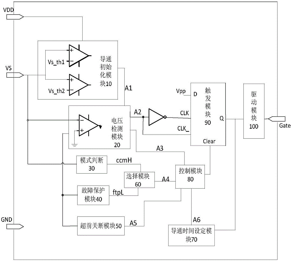
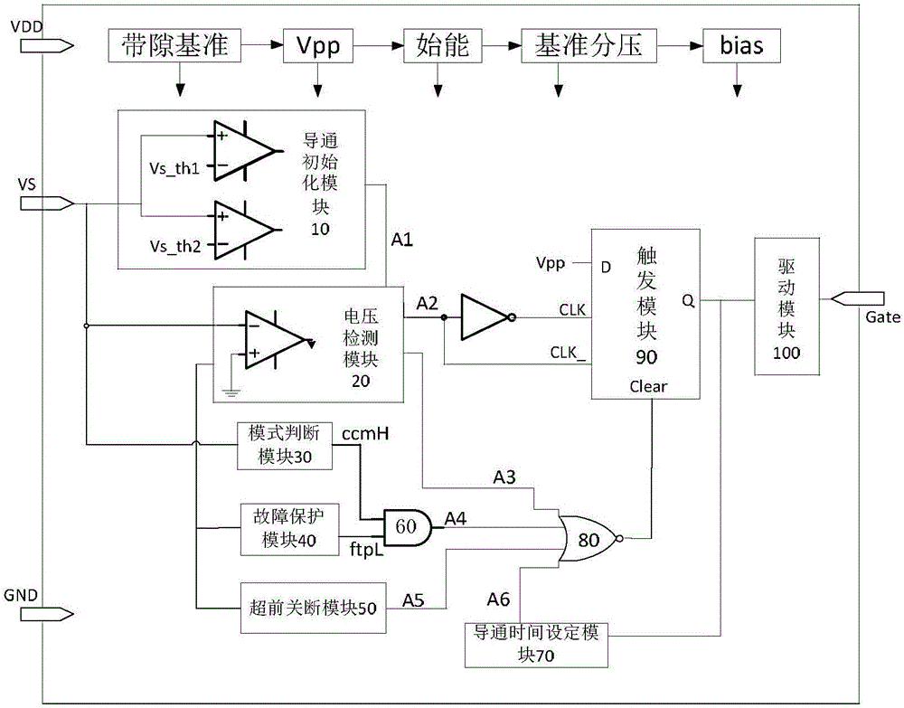
[0033] figure 1 Shown is a schematic structural diagram of the synchronous rectification chip of the present invention, the synchronous rectification chip includes: a conduction initialization module 10, a voltage detection module 20, a mode judgment module 30, a fault protection module 40, an advanced shutdown module 50, a selection module 60, A time setting module 70 , a control module 80 , a trigger module 90 , and a driving module 100 . The conduction initialization module 10, the voltage detection module 20, and the mode judgment module 30 are respectively connected to the voltage input terminal; the conduction initialization module 10 is connected to the voltage detection module 20, and the voltage detection module 20 is respectively connected to the fault The protection module 40, the advance shutdown module 50, the control module 80, and the trigger module 90; the mode judgment module 30 and the fault protection module 40 are connected to the input end of the selection...


PUM


Abstract

The invention discloses a synchronous rectification control circuit, and the circuit comprises a primary side circuit and an auxiliary side circuit. The primary side circuit comprises a primary side inductor, a primary side switching tube, and a primary side sampling resistor. The auxiliary side circuit comprises an auxiliary side inductor, an auxiliary switching tube, an auxiliary side first sampling resistor, an auxiliary side second sampling resistor, an auxiliary side capacitor, an auxiliary side load resistor, and a synchronous rectification control chip. The circuit detects the voltage Vd of a leakage end, connected with an auxiliary switching tube SR_MOSFET, of the auxiliary side inductor in a mode of cycle-by-cycle analogy, can enable an IC in a DCM/CCM mode to precisely control the time point of discharging finishing, effectively judges the switching-off point, achieves an advanced switching-off function, and solves a difficult problem that the precise switching-off cannot be achieved at the DCM/CCM modes at the same time in the prior art. The circuit can simplify the peripheral application circuits, and reduces application devices.

Description

technical field [0001] The invention relates to the field of synchronous rectification, in particular to a synchronous rectification control circuit. Background technique [0002] Synchronous rectification is a technology that uses a dedicated power MOS FFT with extremely low on-state resistance to replace the rectifier diode to reduce rectification loss. Starting from the cut-off time of the primary side switch tube, the secondary side switch tube is turned on, and the secondary side inductor starts to discharge. The side switch tube must be turned off, otherwise it will cause the secondary output capacitor to discharge in reverse, and there is a risk of bombing. [0003] At present, there are several methods to solve the shutdown of the secondary switch tube: [0004] 1. Utilize the conservation of volt-second product: first sample the product of the voltage across the secondary inductance at the moment the primary switch is turned on and the holding time (the voltage ac...

Claims


Application Information

Patent Timeline
Patent Type & Authority Applications(China)
IPC IPC(8): H02M3/335H02H7/12
CPCH02H7/1213H02M3/33592Y02B70/10
Inventor 杨世红熊平
Owner SHAANXI REACTOR MICROELECTRONICS
Why Eureka
Try Eureka