Real-time correction system and method for commutation phase of sensorless brushless DC motor
A brush DC motor, real-time correction technology, applied in the direction of electronic commutation motor control, control system, electrical components, etc., to achieve the effect of stable operation
- Summary
- Abstract
- Description
- Claims
- Application Information
AI Technical Summary
Problems solved by technology
Method used
Image
Examples
Embodiment 1
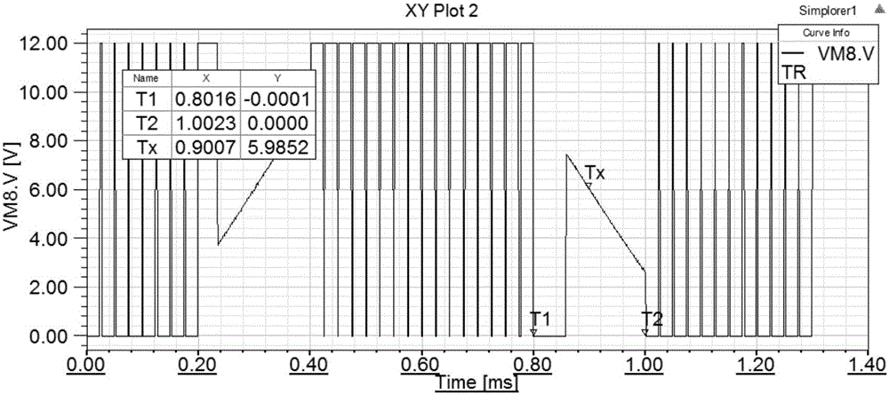
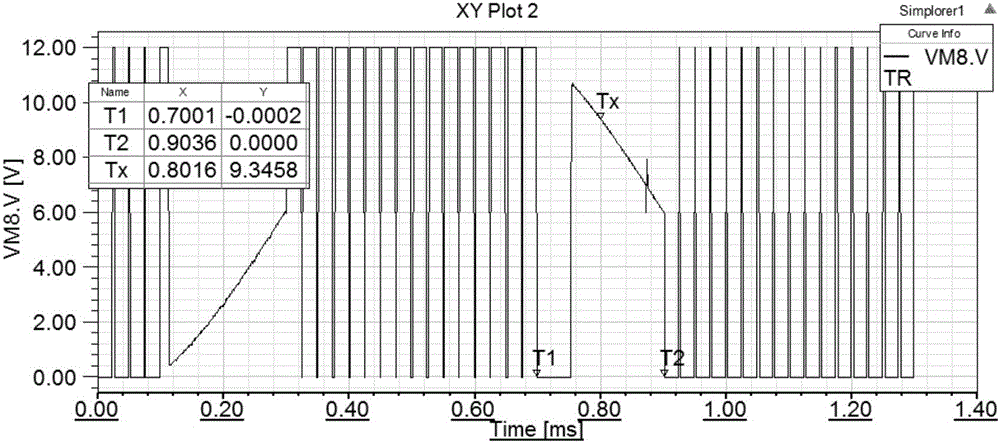
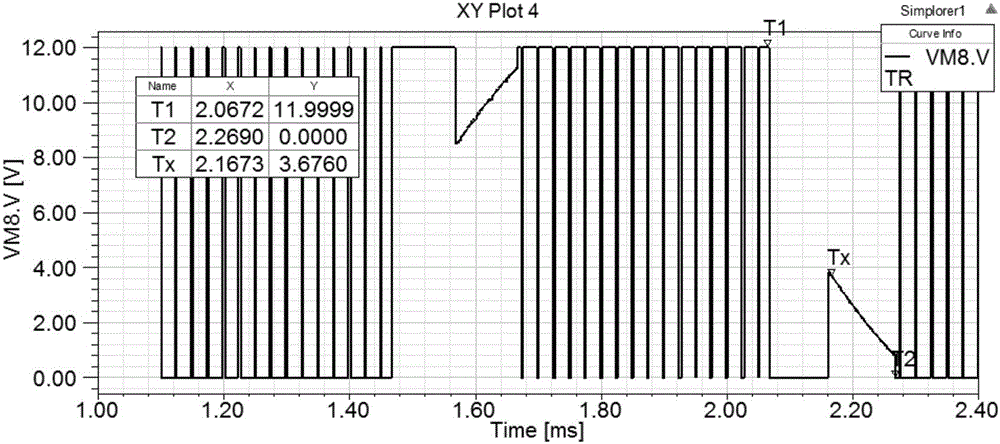
[0077] In this embodiment, an interior permanent magnet brushless DC motor is used for illustration. Brushless DC motor, Bmshless DC Motor, referred to as BLDCM.
[0078] Taking the detection of the A-phase terminal voltage as an example to illustrate the commutation phase correction method of the position sensorless DC brushless motor.
[0079] like figure 1 Shown is the circuit diagram of the three-phase full-bridge drive control circuit brushless DC motor, and the armature winding of the stator of the three-phase full-bridge drive brushless DC motor adopts a star connection structure. The three-phase full-bridge drive control circuit is controlled by two-two conduction mode, which means that the brushless DC motor has two-phase windings conducting at any time, and the other phase winding is in a suspended state, then the power switch Tubes VT1-VT6 have six switch combination states. The phases are commutated every 60° electrical angle, and one power switch tube is switch...
PUM
 Abstract
Description
Claims
Application Information
 - R&D
- Intellectual Property
- Life Sciences
- Materials
- Tech Scout
- Unparalleled Data Quality
- Higher Quality Content
- 60% Fewer Hallucinations
Browse by: Latest US Patents, China's latest patents, Technical Efficacy Thesaurus, Application Domain, Technology Topic, Popular Technical Reports.
© 2025 PatSnap. All rights reserved.Legal|Privacy policy|Modern Slavery Act Transparency Statement|Sitemap|About US| Contact US: help@patsnap.com


