Protection and control system for control rod power supply system

A technology of power supply system and control system, applied in control system, control generator, emergency protection circuit device, etc., can solve the problems such as the inability to demagnetize the rotor circuit, the inability to trip the protection action, and the inability of the main control operator to monitor, etc. The effect of optimizing hard-wired trip circuit and PLC logic, optimizing excitation and de-excitation logic, and improving control and protection design

Inactive Publication Date: 2017-02-22
YANGJIANG NUCLEAR POWER +2
View PDF2 Cites 4 Cited by
  • Summary
  • Abstract
  • Description
  • Claims
  • Application Information

AI Technical Summary

Problems solved by technology

If the Set1 or Set2 PLC device 103 fails, it will cause the outlet switch of the Set1 or Set2 generator to trip, and the generators in this row will continue to run without protection. In the case of PLC failure, it is impossible to manually stop the RAM generator set for troubleshooting
If the PLC device 103 of the public part fails, it will cause the low frequency protection of the generator to fail
When the RAM fails within 5s of the excitation switch of the existing RAM generator, the protection action cannot trip the excitation switch.
In the original PLC logic, the sub-position signal of the de-excitation switch is used as a necessary condition to trigger the trip command of the excitation switch. Therefore, within 5s of 403JA closing, the command to trip the excitation switch cannot be issued due to the 403JA closing position signal, and the rotor circuit cannot De-excitation
[0003] The low-frequency protection of the existing RAM system samples the motor outlet voltage through the PT air switch. If the PT air switch fails and trips, the low-frequency protection loses voltage sampling, and the low-frequency protection trips the outlet, which will cause the reactor control rod to lose control power, resulting in tripping.

Method used


Image

  • Protection and control system for control rod power supply system
  • Protection and control system for control rod power supply system
  • Protection and control system for control rod power supply system

Examples


Embodiment Construction

[0023] In order to make the object, technical solution and advantages of the present invention clearer, the present invention will be further described in detail below in conjunction with the accompanying drawings and embodiments. It should be understood that the specific embodiments described here are only used to explain the present invention, not to limit the present invention.

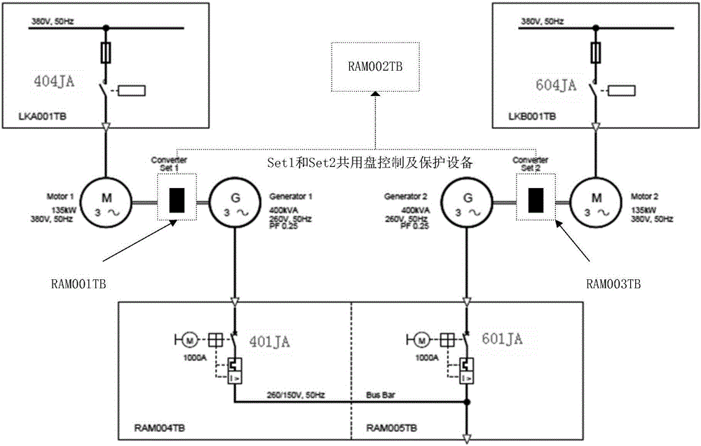
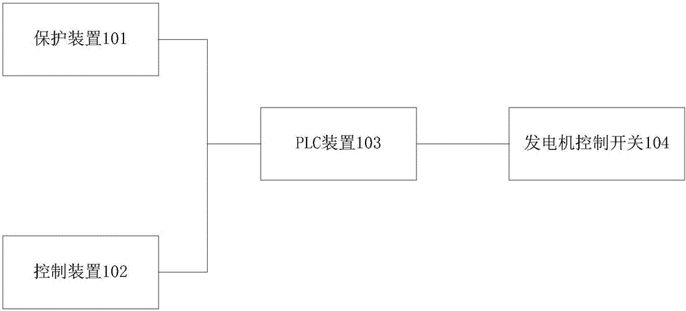
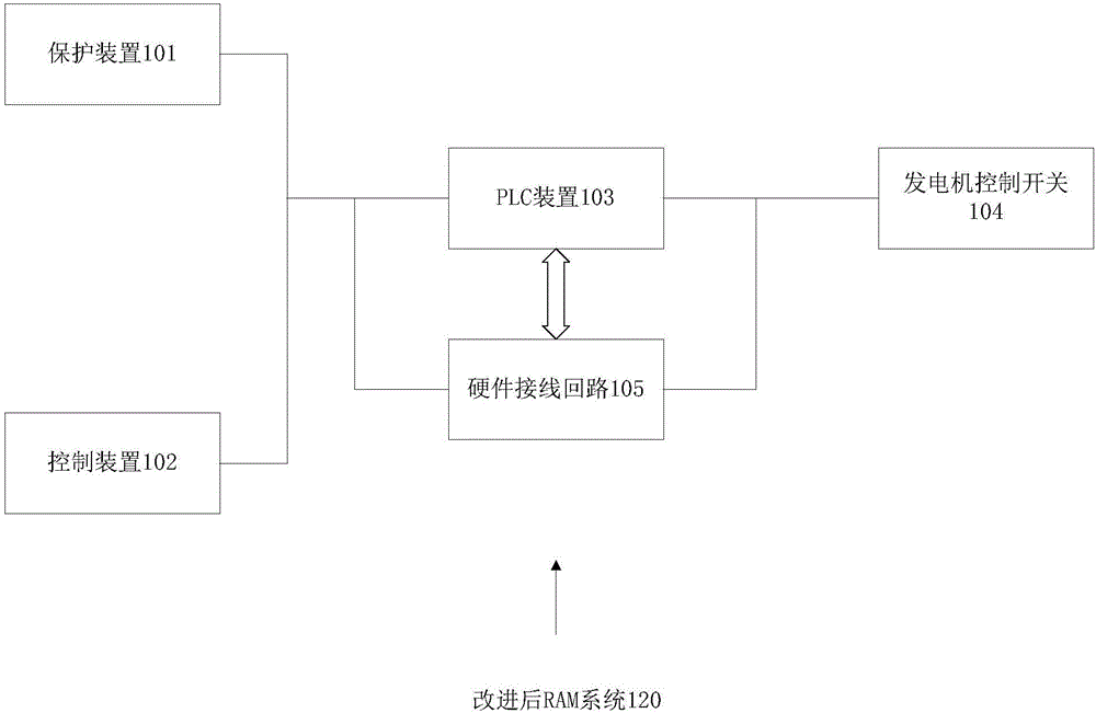
[0024] figure 1 It is a brief schematic diagram of the control rod power supply system protection and control system (RAM system for short) of the nuclear power plant involved in the present invention. The RAM system is applied to two sets of power supply devices of Set1 and Set2. As an example, the RAM system can be installed in three cabinets respectively . The first cabinet RAM001TB is equipped with the control and protection device 101 of the first power supply unit Set1. The protection device 101 includes a generator differential protection device 401, a generator reverse power protection dev...


PUM


Abstract

Disclosed is a protection and control system for a control rod power supply system. The protection and control system comprises a control rod power supply system protection apparatus, a control apparatus for controlling a control switch of a generator according to a signal provided by the protection apparatus, a PLC apparatus for outputting an equipment protection control instruction, and a generator control switch for controlling the starting and stopping of the generator; the protection and control system also comprises a hard-wired protection circuit, an interlocking control switch for automatically switching a protection circuit to the hard-wired protection circuit, a magnetic blow-out switch control apparatus and a low-frequency protection switch control apparatus; and the protection apparatus comprises a generator differential protection apparatus, a generator inversion power protection apparatus, a generator field loss protection apparatus, a generator overcurrent protection apparatus and a low-frequency protection switch. By optimizing low-frequency protection maloperation logic caused by PT air switch tripping, the operational stability of an RAM system is also improved.

Description

technical field [0001] The invention relates to a power supply system protection and control system, in particular to a control rod power supply system protection and control system. Background technique [0002] The task of the control rod power supply system (RAM) in nuclear power plants is to supply power to the control rod drive mechanism, and the control rod power supply system plays a vital role in the operation of nuclear power plants. The existing RAM consists of two sets of power supply units, Set1 and Set2, which are installed in three cabinets respectively. All protection and control logic of the RAM system exits through the PLC device 103 . If the Set1 or Set2 PLC device 103 fails, it will cause the outlet switch of the Set1 or Set2 generator to trip, and the generators in this row will continue to run without protection. In the case of PLC failure, the RAM generator set cannot be manually stopped for troubleshooting. If the PLC device 103 of the public part f...

Claims


Application Information

Patent Timeline
Patent Type & Authority Applications(China)
IPC IPC(8): H02P9/08H02P9/12H02H7/06
CPCH02P9/08H02H7/06H02P9/123
Inventor 黄清林何力王云辉沙忠林林勇朱明彭淼
Owner YANGJIANG NUCLEAR POWER
Why Eureka
Try Eureka