Apparatus and method for parallel video transmission with visible light

A visible light and video technology, used in free space transmission, television, closed-circuit television systems, etc., can solve problems such as loss of original video signals, failure of video signal transmission, and non-real-time transmission of live video, to ensure integrity, avoid Distortion effect

Active Publication Date: 2019-03-26
长春光客科技有限公司
View PDF6 Cites 0 Cited by
  • Summary
  • Abstract
  • Description
  • Claims
  • Application Information

AI Technical Summary

Problems solved by technology

[0002] 2K, 4K and other ultra-high-definition and ultra-high-resolution video technologies have higher requirements for bandwidth, but radio frequency communication cannot meet this requirement
However, existing technologies have not yet fully exploited the high data rate advantages of VLC
For example, a Chinese patent application with application number 201310582529.4 and titled "FPGA-based Visible Light Video Communication System and Method" discloses a solution, which uses FPGA to encode and decode video signals, and uses LED light to wirelessly transmit video signals , to realize the wireless transmission of video signals between two PCs, but this solution only uses visible light communication in the wireless transmission link, so the data transmission rate has not been fully improved, only 10Mbps
In addition, this solution converts the video signal to be transmitted into a video stream signal. In fact, this is the processing of the original video signal, which will cause the loss of the original video signal. The transmission of the video signal cannot achieve both ultra-high speed and no distortion.
Furthermore, the program, as described, only realizes the wireless transmission of video signals between two PCs, and does not transmit live video in real time.

Method used


Image

  • Apparatus and method for parallel video transmission with visible light
  • Apparatus and method for parallel video transmission with visible light
  • Apparatus and method for parallel video transmission with visible light

Examples


Embodiment Construction

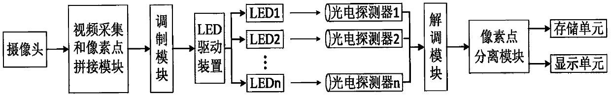
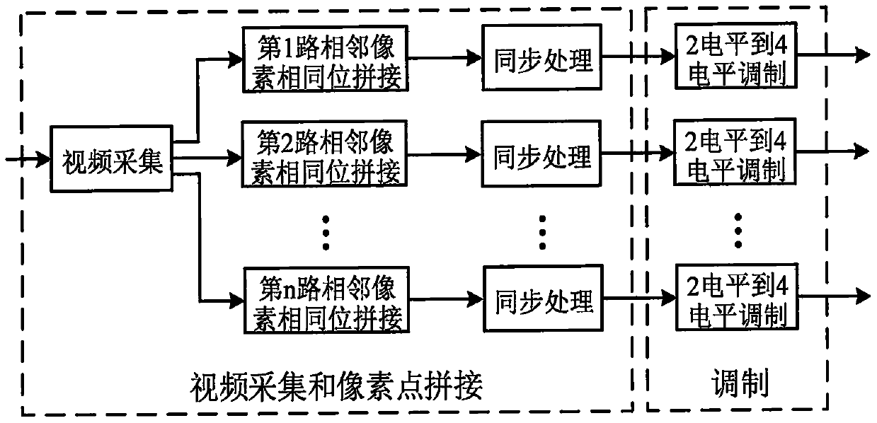
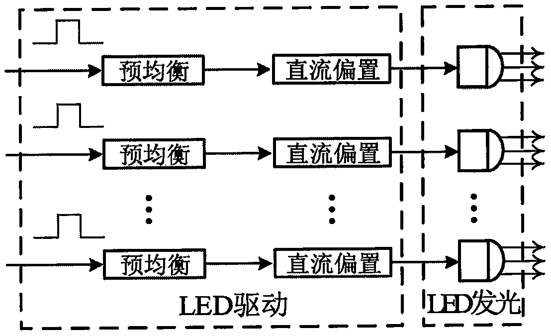
[0008] In the device for transmitting video in parallel with visible light of the present invention, at the transmitting end, the modulation module, the LED driving device, and the LED are sequentially connected; at the receiving end, the photodetector is connected with the demodulation module. Such as figure 1 As shown, the video capture and pixel splicing modules are respectively connected with the camera and the modulation module, and the video capture and pixel splicing modules contain a field programmable gate array (FPGA), such as the Xilinx Zynq-7000 series FPGA, and A synchronous dynamic random access memory (SDRAM), such as DDR3. Several LEDs, such as 8 or 10, are driven by a multi-channel LED driving device. Each of the several LEDs has its own visible light emission wavelength, and the light emitting directions of the several LEDs are consistent. The LED driving device includes a pre-equalization module, such as a digital filter, and a DC bias circuit. A number of...


PUM


Abstract

A device and a method for parallel video transmission based on visible light belong to the technical field of wireless video communication. Real-time, ultrahigh-speed and distortion-free wireless transmission of field video signals has yet to be achieved in the prior art. Based on the fact that a camera can output digital video signals in parallel via multiple channels, video signals are wirelessly transmitted in a multi-channel parallel and multi-transmitter multi-receiver manner through a video acquisition and pixel splicing module, a plurality of LEDs, a plurality of photoelectric detectors, a pixel separation module and the like in the invention. There is no data transmission bottleneck. There is no need for any digital video signal compression processing. The integrity of video signals is ensured, and distortion is avoided. The visible light channels for visible light communication are independent of one another, so that crosstalk in radio-frequency communication is avoided. Meanwhile, compared with radio frequency communication, there is no electromagnetic radiation, no harm is caused to the human body, and the work of other electromagnetic sensitive devices is not hindered.

Description

technical field [0001] The invention relates to a device and method for parallel video transmission with visible light, and belongs to the technical field of wireless video communication. Background technique [0002] 2K, 4K and other ultra-high-definition and ultra-high-resolution video technologies have higher requirements for bandwidth, but radio frequency communication cannot meet this requirement. Compared with radio frequency communication, visible light communication has the basis of high-speed digital communication because the commonly used LED light source can be modulated at high speed; now the data transmission rate of visible light communication has reached 3.4Gbit / s, and the limit data transmission rate of Wi-Fi as radio frequency communication Only 700Mbit / s, therefore, visible light communication is more suitable for video transmission. However, existing technologies have not yet fully exploited the high data rate advantages of VLC. For example, a Chinese pa...

Claims


Application Information

Patent Timeline
Patent Type & Authority Patents(China)
IPC IPC(8): H04B10/116H04N7/18
CPCH04B10/116H04N7/181
Inventor 蒋余成倪小龙姚海峰刘智刘艺张红玲王素芬
Owner 长春光客科技有限公司
Why Eureka
Try Eureka