Charged particle beam therapy and magnetic resonance imaging

A magnetic resonance imaging and particle beam technology, applied in the field of target area, can solve problems such as image distortion

Active Publication Date: 2017-02-22
KONINKLJIJKE PHILIPS NV
View PDF7 Cites 10 Cited by
  • Summary
  • Abstract
  • Description
  • Claims
  • Application Information

AI Technical Summary

Problems solved by technology

This magnetic field will cause image distortion and other artifacts

Method used


Image

  • Charged particle beam therapy and magnetic resonance imaging
  • Charged particle beam therapy and magnetic resonance imaging
  • Charged particle beam therapy and magnetic resonance imaging

Examples


Embodiment Construction

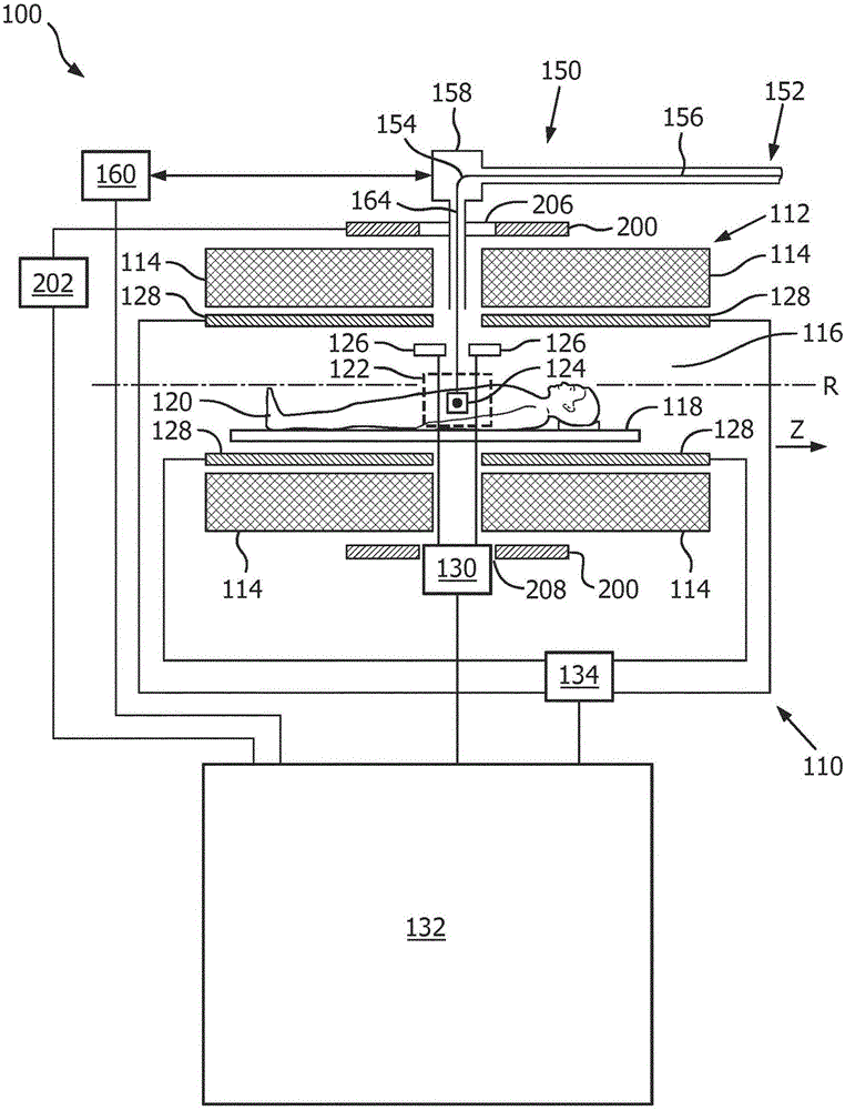
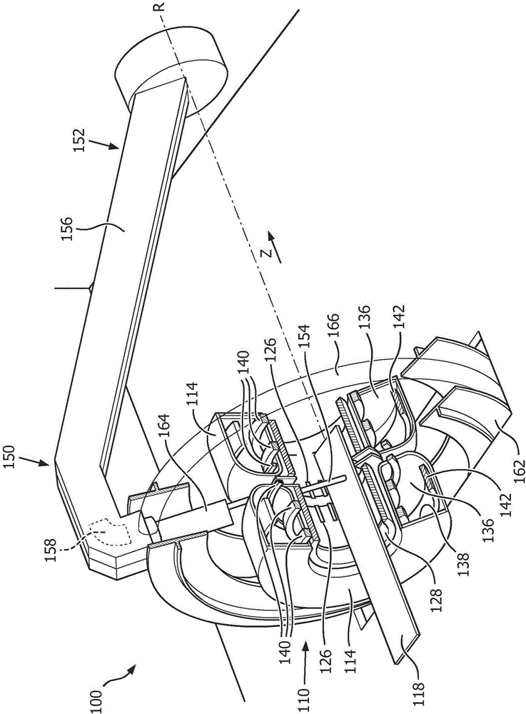
[0051] figure 1 and 2 A medical device 100 according to a preferred embodiment is shown.

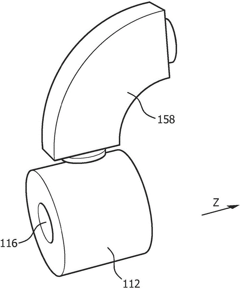
[0052] The medical device 100 includes a magnetic resonance imaging (MRI) system 110 that includes a magnetic resonance (MR) magnet 112 (also referred to as a main magnet) arranged in a manner having two sub-magnets 114 Split magnets. as in figure 2 As can be seen in detail in , each sub-magnet 114 includes a cryogenic chamber 136 provided with a radiation shield 138 . Inside the cryogenic chamber 136 are arranged an inner superconducting coil 140 and an outer superconducting shielding coil 142 suitable for generating a main magnetic field. The superconducting shield coil 142 is adapted such that there is a region of zero magnetic field surrounding the sub-magnet 114 .

[0053] Inside the bore 116 of the sub-magnet 114 there is provided a support 118 suitable for receiving a subject 120 of interest. Between the two sub-magnets 114 there is an imaging volume 122 in which the magnet...


PUM


Abstract

The invention discloses a charged particle beam therapy and a magnetic resonance imaging. The present invention provides a medical apparatus (100) comprising a magnetic resonance imaging system (110) for acquiring magnetic resonance data from an imaging volume (122) covering at least partially a subject of interest (120), wherein the magnetic resonance imaging system (110) comprises a main magnet (112) for generating a magnetic field within the imaging volume (122), a particle beam apparatus (150) having a particle beam line (152) for a particle beam (154) of charged particles, including a gantry (156) configured for rotating around a rotational axis (R), which is arranged in the longitudinal direction of the main magnet (112), wherein the gantry (156) comprises at least one bending magnet (158) for directing the particle beam (154) to an irradiation volume (124) within the imaging volume (122), an active compensation coil (200), which is arranged to substantially surround at least the imaging volume (122), and a control unit (132) for controlling the active compensation coil (200) for canceling a stray field caused by the at least one bending magnet (158) within the imaging volume (122) at least in the longitudinal direction of the main magnet (112).The present invention also provides a shielding method for use in the above medical apparatus (100).

Description

technical field [0001] The present invention relates to the field of guiding charged particles to a target region in a subject of interest, wherein the particles are guided using magnetic resonance imaging. Background technique [0002] In charged particle beam therapy, a high energy charged particle beam is directed at a target area of ​​a subject. The basic mechanism for the interaction of a beam comprising charged particles with matter is through the Coulomb force. As the relative velocity of the two particles decreases, the cross section of the Coulomb impact increases. As the beam of charged particles passes through the subject, it loses energy faster and faster. The effect of this is that most of the energy of the particle beam is deposited near the end of the beam path. Therefore, a peak of energy is deposited at the end of the beam path, which is called the Bragg peak. [0003] Charged particle beam therapy thus allows very precise delivery of high doses to a tar...

Claims


Application Information

Patent Timeline
Patent Type & Authority Applications(China)
IPC IPC(8): A61N5/10
CPCA61N5/1049A61N2005/1055A61N2005/1087G01R33/3875G01R33/3806G01R33/4808A61B5/055A61N5/1081
Inventor J·A·奥弗韦格
Owner KONINKLJIJKE PHILIPS NV
Why Eureka
Try Eureka