Efficient compact fusion reactor

A reactor and compact technology, applied in fusion reactors, thermonuclear fusion reactors, nuclear reactors, etc., can solve the complex problems of producing fusion energy

Inactive Publication Date: 2017-02-22
TOKAMAK ENERGY
View PDF5 Cites 15 Cited by
  • Summary
  • Abstract
  • Description
  • Claims
  • Application Information

AI Technical Summary

Problems solved by technology

[0002] The challenge of producing fusion energy is complex
A number of alternatives to tokamaks have been propo

Method used


Image

  • Efficient compact fusion reactor
  • Efficient compact fusion reactor
  • Efficient compact fusion reactor

Examples


Embodiment Construction

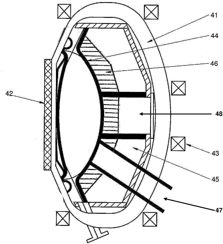
[0045] The present application is based on a very compact form of the tokamak and employs a series of innovative features, including the optimization of the alpha confinement at unexpectedly low plasma currents. The aim of the "Efficient Compact Fusion Reactor" (ECFR) is to provide a compact fusion power plant.

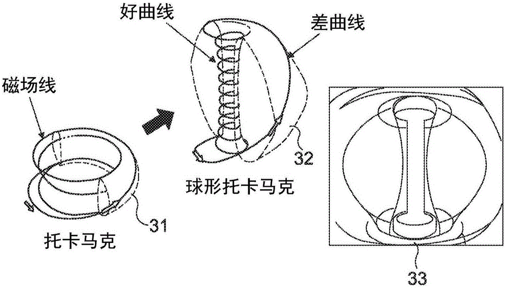
[0046] When a deuterium-tritium (D-T) or deuterium-deuterium (D-D) plasma becomes very hot, atomic nuclei fuse together, producing fusion neutrons and releasing high-energy neutrons. So far, the most promising way to achieve this goal is to use a tokamak; in polymerization using traditional tokamak methods (as implemented by ITER), the plasma needs to have high confinement time, high temperature and High density to optimize this process.

[0047] Tokamak is based on a strong circular magnetic field B T and high plasma current I P is characterized by the combination of a large plasma volume and significant auxiliary heating to provide a thermally stable plasma that ...


PUM

PropertyMeasurementUnit
Radiusaaaaaaaaaa
Electric currentaaaaaaaaaa

Abstract

An efficient compact nuclear fusion reactor for use as a neutron source or energy source is described. The reactor comprises a toroidal plasma chamber and a plasma confinement system arranged to generate a magnetic field for confining a plasma in the chamber. The plasma confinement system is configured so that a major radius of the confined plasma is 1.5m or less. The toroidal magnetic field is operated 5T or less and the plasma current is 5 MA or less. Despite this, [Alpha]-particles generated are confined in the plasma.

Description

technical field [0001] The invention relates to a compact fusion reactor operating in a strong annular field. In particular, but not exclusively, the invention relates to a spherical tokamak reactor suitable for use as an energy source or as a high-efficiency neutron source. Background technique [0002] The challenges of producing fusion energy are complex. Many alternatives to tokamaks have been proposed, although none have yet produced results comparable to the best tokamaks currently in operation, such as JET. [0003] After starting the construction of ITER, the largest and most expensive (c15bn euro) tokamak in history, the world's nuclear fusion research has entered a new stage. A successful route to commercial fusion reactors requires long pulses, high efficiencies that make electricity generation economical, and stable operation. These three conditions are particularly difficult to achieve simultaneously, and the planned scenario would require years of experiment...

Claims


Application Information

Patent Timeline
IPC IPC(8): G21B1/05H05H1/12
CPCG21B1/057H05H1/12Y02E30/10
Inventor 阿兰·赛克斯米哈尔·格瑞亚耐维奇大卫·金厄姆
Owner TOKAMAK ENERGY
Why Eureka
Try Eureka