Method for plasma-cutting a workpiece by means of a plasma-cutting system and pulsating current

A technology of cutting equipment and cutting current, which is applied to plasma welding equipment, welding equipment, metal processing equipment, etc., and can solve problems such as replacement and electrode damage

Active Publication Date: 2012-07-11
KJELLBERG FINSTERWALDE PLASMA & MASCH GMBH
View PDF6 Cites 9 Cited by
  • Summary
  • Abstract
  • Description
  • Claims
  • Application Information

AI Technical Summary

Problems solved by technology

In this way, the entire electrode is destroyed and must be replaced

Method used


Image

  • Method for plasma-cutting a workpiece by means of a plasma-cutting system and pulsating current
  • Method for plasma-cutting a workpiece by means of a plasma-cutting system and pulsating current
  • Method for plasma-cutting a workpiece by means of a plasma-cutting system and pulsating current

Examples


Embodiment Construction

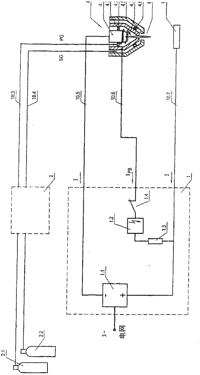
[0057] figure 1 A schematic diagram of a plasma cutting system according to the prior art is shown, which has a plasma current source 1 whose components are a current source 1.1, an igniter 1.2, a resistor 1.3 and contacts 1.4. The negative pole of the current source utilizes lead 10.5 to be connected with the electrode 4.1 of plasma burner 4, and positive pole is connected with workpiece 5 through lead 10.7 and is connected with the nozzle 4.2 of plasma burner 4 through lead 10.6 by resistance 1.3, igniter 1.2 and contact 1.4. The plasma current source is usually powered by a three-phase AC grid, such as 400V / 50Hz. The gas supply of the plasma burner is realized here via the gas console 2, in which there may be valves, such as magnetic valves and / or regulating valves (not shown), for switching the gas, in particular the plasma gas PG, and the secondary Gas SG. The gas supply takes place in this example via a gas cylinder 2.1 for the plasma gas and a gas cylinder 2.2 for the...


PUM


Abstract

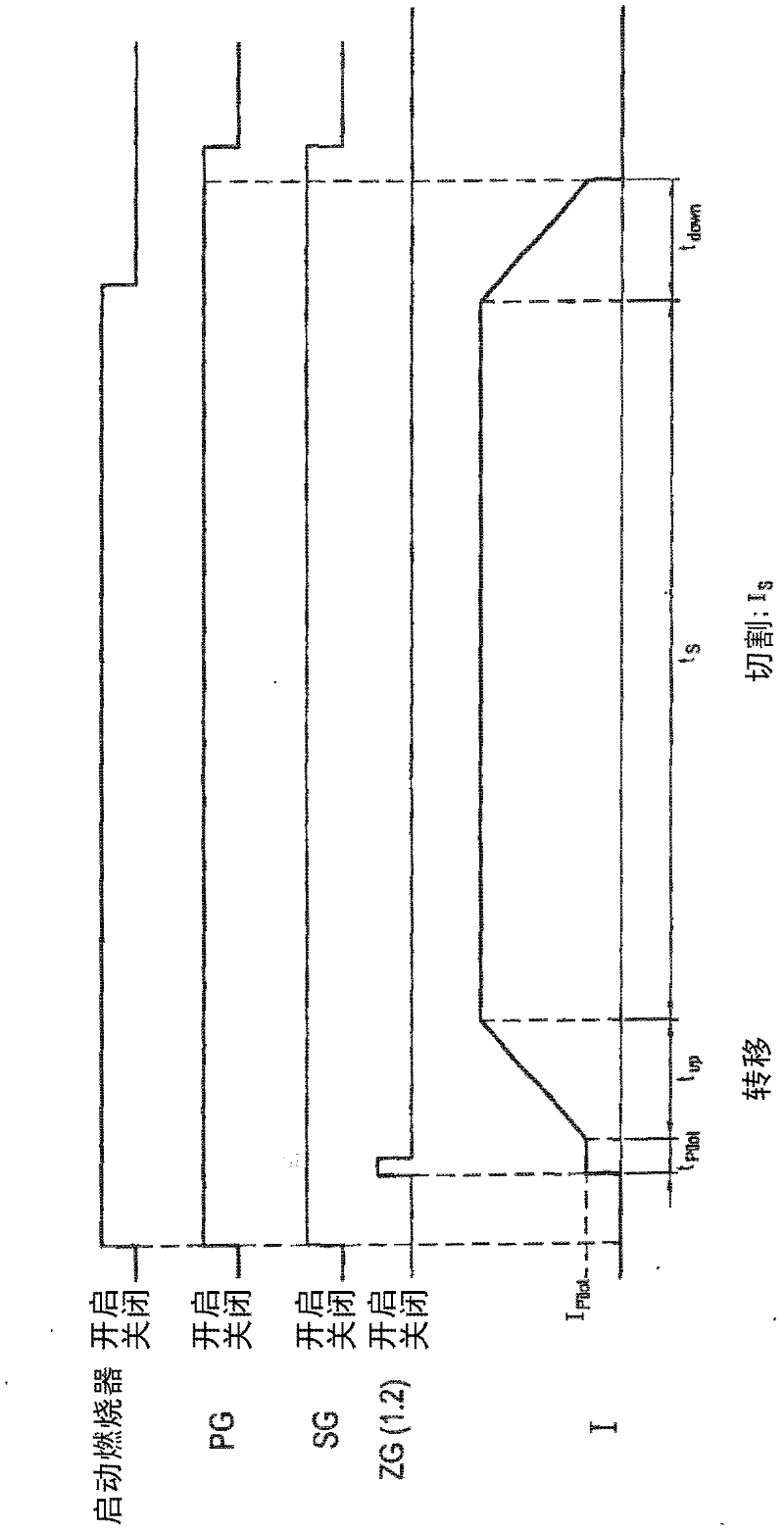
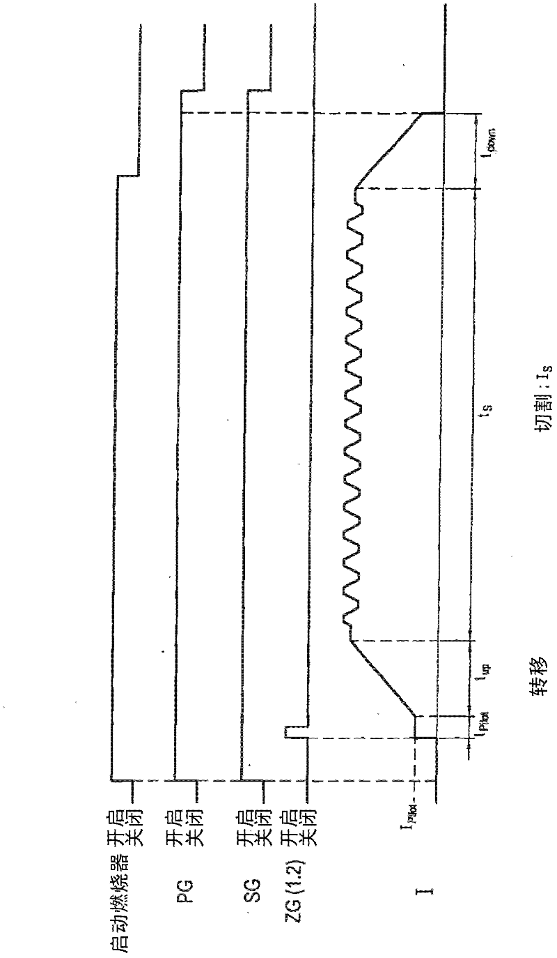
The invention relates to a method for plasma-cutting a workpiece by means of a plasma-cutting system, which comprises a plasma current source and a plasma torch, which has an electrode and a nozzle, which has a small distance from the electrode at a lower end of the plasma torch in order to form a plasma chamber therebetween, characterized in that a current I produced by the plasma current source and flowing through the plasma torch is brought to pulsation in a targeted or controlled manner at an arbitrary frequency f in the range of 30 Hz to 500 Hz, preferably 35 Hz to 500 Hz, especially preferably 55 Hz to 400 Hz, at least during a partial time period of the plasma-cutting process, or a current I produced by the plasma current source and flowing through the plasma torch is brought to pulsation in a targeted or controlled manner at an arbitrary frequency f in the range of 0.1 Hz to 30 Hz, preferably 0.1 Hz to 29 Hz, especially preferably 0.1 Hz to 20 Hz, at least during a partial time period of the plasma-cutting process.

Description

technical field [0001] The invention relates to a method for plasma cutting workpieces by means of a plasma cutting device comprising a plasma current source and a plasma burner having an electrode and a nozzle connected to a The electrodes have a small spacing to form a plasma chamber between them. Background technique [0002] A thermally highly heated electrically conductive gas, called a plasma, is composed of positive and negative ions, electrons, and excited and neutral atoms and molecules. [0003] Various gases, such as monoatomic argon and / or diatomic gases hydrogen, nitrogen, oxygen or air, are used as plasma gases. These gases are ionized and dissociated by the energy of the arc. The constricted arc through the nozzle is called the plasma beam. [0004] The plasma beam can be greatly influenced in its parameters by the shaping of the nozzle and electrodes. Such parameters of the plasma beam are, for example, beam diameter, temperature, energy density and gas f...

Claims


Application Information

Patent Timeline
Patent Type & Authority Applications(China)
IPC IPC(8): B23K10/00
CPCB23K10/006B23K10/00
Inventor 延斯·弗里德尔格哈德·伊尔冈沃尔克·科林克延斯·奥曼
Owner KJELLBERG FINSTERWALDE PLASMA & MASCH GMBH
Why Eureka
Try Eureka