
Light-emitting device package

A light-emitting device packaging and light-emitting device technology, which is applied in the direction of semiconductor devices, electric solid devices, electrical components, etc., can solve the problems of fading, deterioration of the life and performance of light-emitting device packaging, and achieve the effect of increasing bonding force and excellent waterproof

Active Publication Date: 2017-02-22
SUZHOU LEKIN SEMICON CO LTD
View PDF7 Cites 2 Cited by
  • Summary
  • Abstract
  • Description
  • Claims
  • Application Information

AI Technical Summary

Problems solved by technology

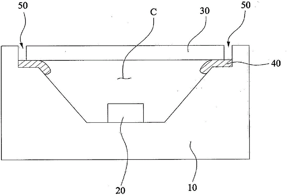
However, when the external foreign matter 50 is in a gaseous state, for example, when gas molecules including water molecules permeate from the outside, it may be difficult for the adhesive 40 to completely block the gas molecules.
In particular, when the light emitting device package is operated for a long time in a high temperature and high humidity environment, for example, moisture or water may enter the cavity C, thereby causing discoloration of, for example, the plating portion of the light emitting device package and the electrode portion of the LED 20, which may further Deteriorating lifetime and performance of light emitting device packages

Method used


Image

  • Light-emitting device package
  • Light-emitting device package
  • Light-emitting device package

Examples


Embodiment Construction

[0039] Hereinafter, in order to specifically describe the present disclosure and facilitate understanding of the present disclosure, the embodiments will be described in detail with reference to the accompanying drawings. However, the embodiments disclosed herein may be changed in various other forms, and the scope of the present disclosure should not be construed as being limited to these embodiments. The embodiments disclosed herein are provided so that this disclosure will be more fully described to those of ordinary skill in the art.

[0040] In describing the embodiments disclosed herein, it will be understood that when an element is referred to as being formed "on" or "under" another element, it can be directly on or "under" another element, Or formed indirectly with one or more elements interposed therebetween. It should also be understood that elements may be described as being "on" or "under" with respect to the figures.

[0041] In the drawings, the thickness or si...


PUM


Abstract

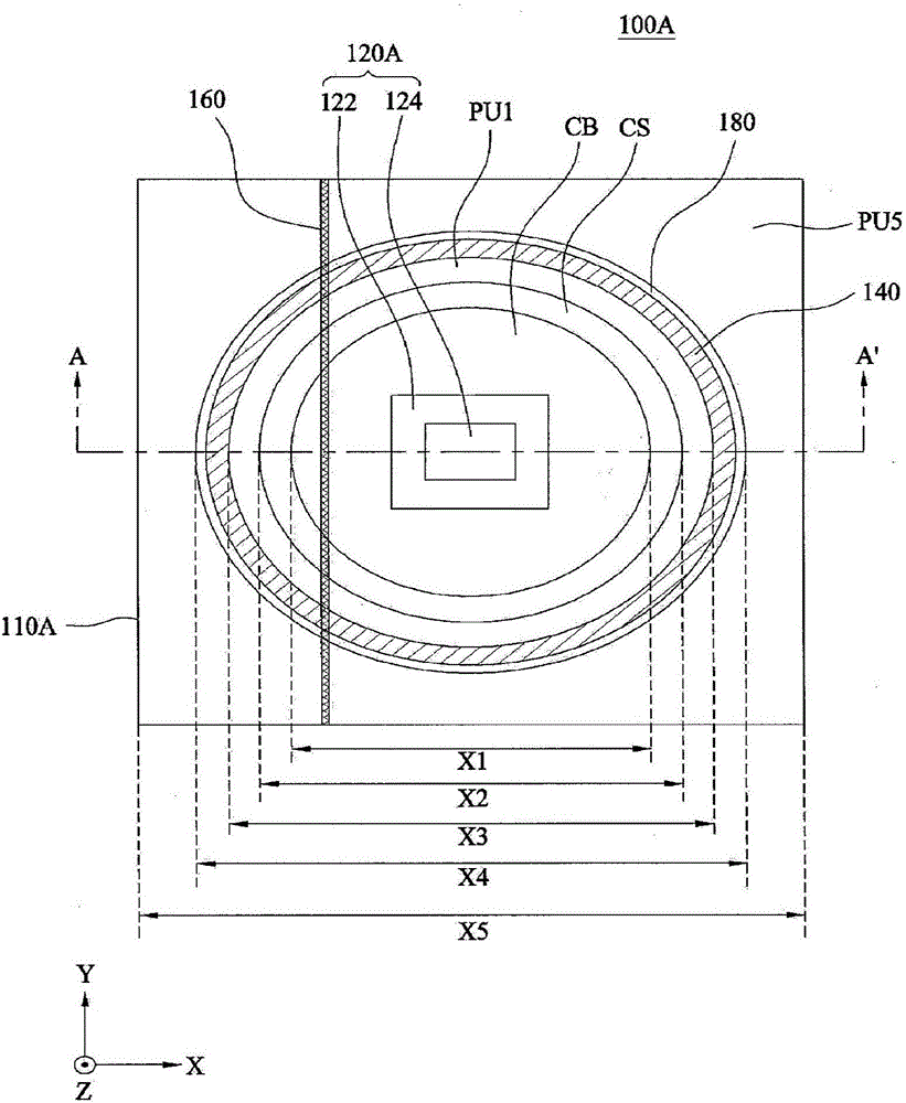
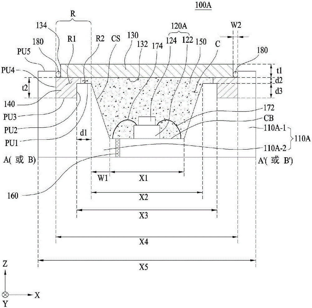
A light-emitting device package according to an embodiment comprises: a package body which comprises a cavity and a recess part, the recess part being formed on the circumference of the cavity and having at least one concave portion; at least one light-emitting device which is mounted within the cavity; a light-transmitting member which is arranged so as to cover the upper section of the cavity and transmits light emitted from the at least one light-emitting device; and a bonding member which is received in the at least one concave portion so as to bond the light-transmitting member and the package body in the recess part.

Description

technical field [0001] Embodiments relate to a light emitting device package. Background technique [0002] Red, green and blue light emitting diodes (LEDs) that can achieve very bright white light have been developed based on, for example, the development of gallium nitride (GaN) metal organic chemical vapor deposition methods and molecular beam growth methods. [0003] Because these LEDs do not include environmentally harmful substances such as mercury (Hg) used in conventional lighting fixtures such as incandescent lamps and fluorescent lamps, they are very environmentally friendly, while also having several advantages such as long life and low power consumption, So these LEDs replace traditional light sources. The significant competitiveness of LED is to achieve high brightness through high efficiency and high output chip and packaging technology. [0004] figure 1 is a schematic cross-sectional view of a conventional light emitting device package, which includes a pa...

Claims


Application Information

Patent Timeline
Patent Type & Authority Applications(China)
IPC IPC(8): H01L33/54
CPCH01L2924/181H01L2224/48091H01L33/486H01L33/52H01L33/58H01L2924/00012H01L2924/00014H01L33/483
Inventor 金炳穆金夏罗小平洋金伯俊李廷祐黄相雄
Owner SUZHOU LEKIN SEMICON CO LTD
Learn More