Debris flow step-by-step filtration system

A filtration system and debris flow technology, applied in marine engineering, construction, hydraulic engineering equipment, etc., can solve the problems of increasing sediment pressure, increasing the suction height of turbines, increasing reservoir submergence, immersion loss, etc., to reduce the destructive force.

Inactive Publication Date: 2017-03-08
JILIN UNIV
View PDF8 Cites 10 Cited by
  • Summary
  • Abstract
  • Description
  • Claims
  • Application Information

AI Technical Summary

Problems solved by technology

The impact of sediment deposition on the reservoir is manifested as: encroachment and adjustment of storage capacity, reduction of comprehensive utilization benefits; the extension of the end of sedimentation, raising the return water level, increasing reservoir submersion and immersion loss; silting in front of the dam increases the mud that acts on hydraulic structures Sand pressure hinders the normal operation of ship locks and water intakes; chemical substances precipitate with sedimentation, pollute water quality, and affect the growth of aquatic organisms; sedimentation makes the discharge flow clear, causing erosion and deformation of the downstream riverbed, making it difficult to obtain water downstream, and Increasing the suction height of the turbine is not conducive to the operation of the hydropower station
In addition, silted reservoirs may face the problem of dam demolition, causing economic losses

Method used


Image

  • Debris flow step-by-step filtration system
  • Debris flow step-by-step filtration system
  • Debris flow step-by-step filtration system

Examples


Embodiment Construction

[0024] The following will clearly and completely describe the technical solutions in the embodiments of the present invention with reference to the accompanying drawings in the embodiments of the present invention. Obviously, the described embodiments are only some, not all, embodiments of the present invention. Based on the embodiments of the present invention, all other embodiments obtained by persons of ordinary skill in the art without creative efforts fall within the protection scope of the present invention.

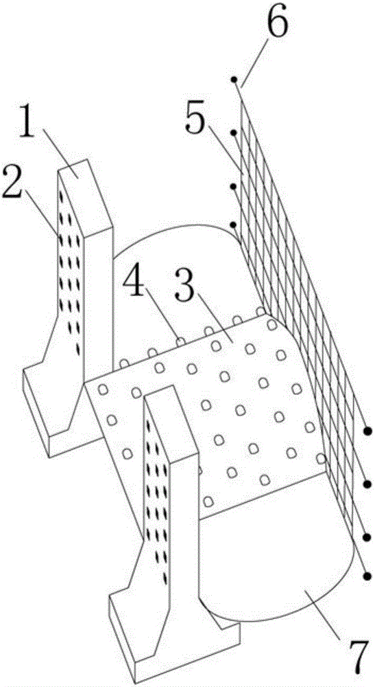
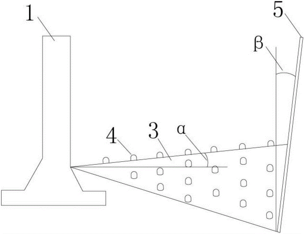
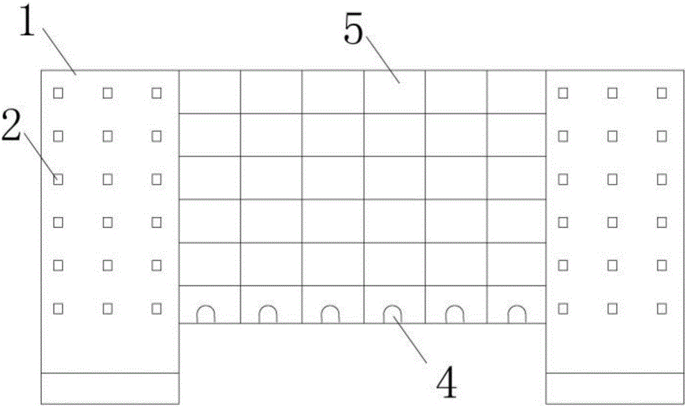
[0025] see Figure 1-7 As shown, the present invention is a step-by-step filtration system for debris flow. The system is composed of a plurality of debris flow filtering devices arranged on the debris flow ditch bed. The debris flow filtering device includes a deceleration platform 3, and the two sides of the deceleration platform 3 near the upstream end are provided with The retaining dam 1, the retaining dam 1 is fixed in the depth of the debris flow ditch bed t...


PUM


Abstract

The invention discloses a debris flow step-by-step filtration system. The system is composed of a plurality of debris flow filtering devices arranged on a debris flow gully. Each debris flow filtering device comprises a speed reduction platform, wherein the two sides of the end, close to the upstream, of the speed reduction platform are provided with blocking dams which are fixed to the deep of the debris flow gully through bases arranged at the bottom; the end, close to the downstream, of the speed reduction platform is connected with a filter screen; the two sides of the filter screen are provided with anchor rods anchored into the debris flow gull; the two sides of the speed reduction platform are provided with slit stopping sites which are formed by defining the blocking dams, the speed reduction platform, the filter screen and mountains on the two sides of the debris flow gully. The debris flow step-by-step filtration system can conduct multiple times of separation on stones, silts and sundries in debris flow step by step, debris flow subjected to multiple times of separation can be changed into flood with extremely low sand content, and destructive force is greatly reduced. Flood can be directly led into a reservoir. The debris flow step-by-step filtration system is particularly applicable to regions with reservoirs on the downstream.

Description

technical field [0001] The invention relates to the field of mud-rock flow control, in particular to a mud-rock flow step-by-step filtration system. Background technique [0002] my country is a mountainous country, and the mountainous area accounts for 70% of the country's land area. According to statistics, the area of ​​debris flow activity in my country has reached 4.3 million km 2 , with more than 8,500 debris flow ditches, it is one of the countries with the largest number of debris flows and the most serious damage in the world. Due to its complex formation process, sudden outbreak, fast flow rate / large material capacity, ferocious onset, short duration, and strong destructive power, debris flow has become a major disaster in mountainous economic construction. At present, debris flow engineering prevention and control is the most effective means of disaster reduction. The prevention and control measures of traditional debris flow engineering can be roughly divided i...

Claims


Application Information

Patent Timeline
Patent Type & Authority Applications(China)
IPC IPC(8): E02B1/00E02B8/06E02B8/02E02B7/02
CPCE02B1/00E02B7/02E02B8/023E02B8/06
Inventor 秦胜伍吕江峰李广杰彭帅英朴晶
Owner JILIN UNIV
Why Eureka
Try Eureka