Air discharging control device and method for train braking

A technology for control devices and trains, applied in the direction of electric fluid pressure control, etc., can solve the problems of unable to stabilize the exhaust air speed control, and achieve the effect of stable exhaust air control speed and continuous adjustment of exhaust air speed

Active Publication Date: 2017-03-08
HANGZHOU CHUANGLIAN ELECTRONICS TECH
View PDF8 Cites 2 Cited by
  • Summary
  • Abstract
  • Description
  • Claims
  • Application Information

AI Technical Summary

Problems solved by technology

[0006] The purpose of the present invention is to overcome the deficiency that the train control vehicle-mounted equipment in the prior art cannot stably exhaust air and control the speed, and provide a train brake exhaust control device and method that can realize stable exhaust air control and speed control

Method used


Image

  • Air discharging control device and method for train braking
  • Air discharging control device and method for train braking
  • Air discharging control device and method for train braking

Examples


Embodiment 1

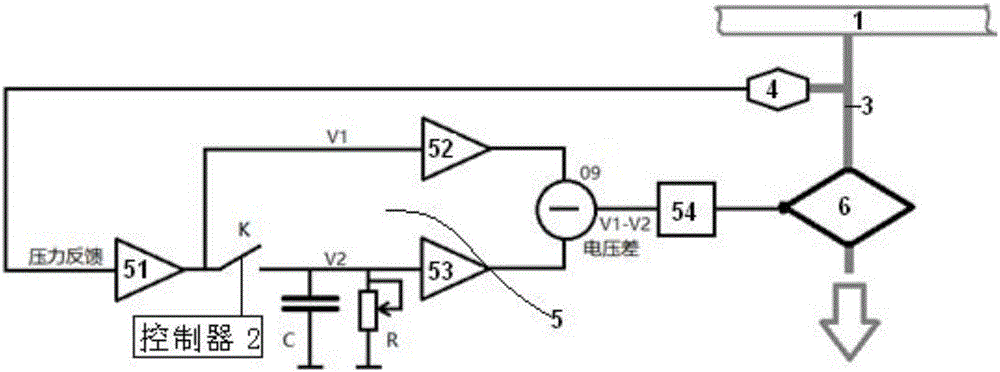
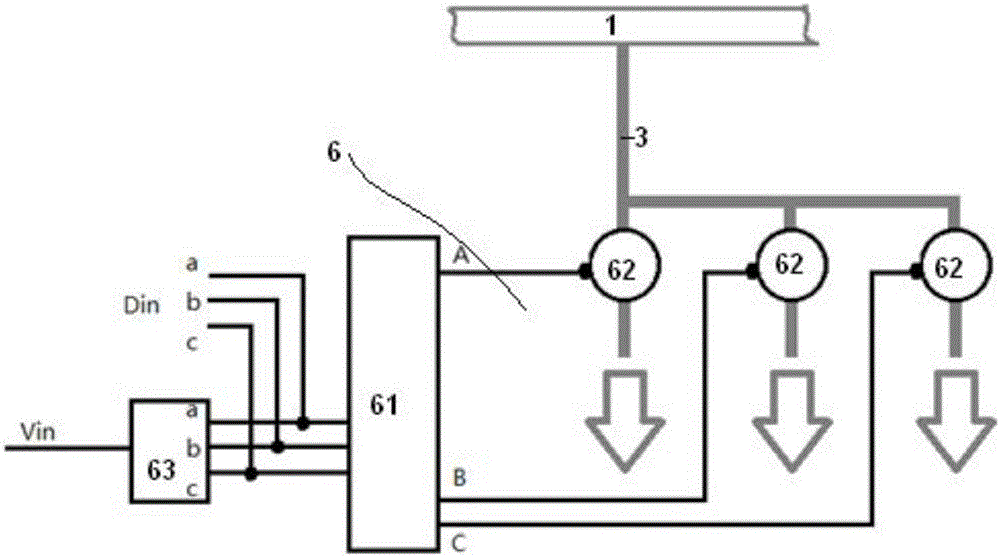
[0052] Such as figure 1 , image 3 The shown embodiment is a kind of exhaust air control device for train braking, comprising a train pipe 1 arranged on the train, a controller 2, a pipeline 3 communicated with the train pipe, a pressure sensor 4 arranged on the pipeline, and a pressure sensor 4 arranged on the pipeline. Feedback control circuit 5, the flow control body 6 located at the front of the exhaust port of the pipeline; the flow control body includes a drive circuit 61, 3 parallel electrically controlled on-off valves 62, the signal input end of the pressure feedback control circuit and the pressure sensor The signal output terminals are electrically connected, the pressure feedback control circuit is electrically connected to the controller and the drive circuit, and the drive circuit is respectively connected to each electronically controlled switch valve.

[0053] The channel cross-sectional areas of the three parallel electrically controlled on-off valves are a, ...

Embodiment 2

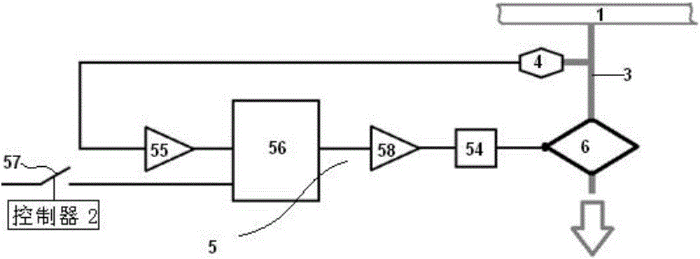
[0067] Such as figure 2 As shown, the pressure feedback control circuit includes an analog-to-digital converter 55, a single-chip microcomputer 56, a second control switch 57 and a digital-to-analog converter 58; the analog-to-digital converter, the single-chip microcomputer, the digital-to-analog converter and the drive circuit are electrically connected in sequence, and the The signal output terminal is electrically connected to the signal input terminal of the digital-to-analog converter, and the two ends of the second control switch are respectively connected to the controller and the single-chip microcomputer. The other structural parts of Embodiment 2 are the same as those in Embodiment 1.

[0068] A method for an exhaust control device for train braking, comprising the steps of:

[0069] The controller is equipped with 7 flow control body cross-sectional areas composed of the channel cross-sectional areas of 3 parallel-connected electronically controlled on-off valves...

Embodiment 3

[0076] Embodiment 3 includes all structures and method parts in Embodiment 1, and Embodiment 3 also includes a processor located between the pressure sensor and the first signal amplifier, and also includes the following steps:

[0077] In the processor, the detection signal of the pressure sensor is processed as follows:

[0078] For each moment t in the detection signal, the computer calculates the voltage amplitude mean value VU(t), the voltage amplitude maximum value MA(t) and the voltage amplitude minimum value MI(t) from the time t-T to the time t;

[0079] set up

[0080]

[0081]

[0082]

[0083]

[0084] in,

[0085] The processor sends the corrected detection signal V(t) to the first signal amplifier.


PUM


Abstract

The invention discloses an air discharge control device and method for train braking. The control device comprises a train pipe arranged on a train, a controller, a pipeline communicated with the train pipe, a pressure sensor arranged in the pipeline, a pressure feedback control circuit and a flow control body arranged in front of an air exhaust opening of the pipeline; the flow control body comprises a driving circuit and m electric-control switch valves in parallel connection, and m>=2; and the signal input end of the pressure feedback control circuit is electrically connected with the signal output end of the pressure sensor, the pressure feedback control circuit is electrically connected with the controller and a drive circuit, and the driver circuit is connected with the electric-control switch valves. The control device and method are characterized in that the air discharge speed can be controlled stably and adjusted continuously.

Description

technical field [0001] The invention relates to the technical field of rail vehicle brakes, in particular to an exhaust air control device and method capable of realizing stable air exhaust and speed-controlled train braking. Background technique [0002] The braking method of rail vehicles mainly adopts the air brake system. During the operation of the vehicle, the driver manipulates the brake valve to discharge the air in the train pipe, so that the pressure of the train pipe decreases, and the brake of the vehicle is controlled to achieve the purpose of deceleration and parking. [0003] When the vehicles are formed into a train, the train pipes of each car are connected into one body, and the pressure in the train pipe is controlled by the locomotive driver to achieve the purpose of controlling the synchronous braking and relief of the whole train. [0004] The on-board train control equipment is a kind of on-board safety equipment configured on the locomotive. It mainly...

Claims


Application Information

Patent Timeline
Patent Type & Authority Applications(China)
IPC IPC(8): G05D16/20
CPCG05D16/20
Inventor 李秀英傅天耀俞仲勋朱有田
Owner HANGZHOU CHUANGLIAN ELECTRONICS TECH
Why Eureka
Try Eureka