Rectangular pin element coarse positioning method based on corner points

A pin component and rough positioning technology, applied in the field of image processing, can solve the problems of light sensitivity, low execution efficiency, and poor versatility of component positioning algorithms, and achieve the effect of stability, high performance, and high versatility

Active Publication Date: 2017-03-08
HARBIN INST OF TECH
View PDF5 Cites 13 Cited by
  • Summary
  • Abstract
  • Description
  • Claims
  • Application Information

AI Technical Summary

Problems solved by technology

[0005] The present invention aims to solve the problem of poor versatility, low execution efficiency and sensitivity to light i

Method used


Image

  • Rectangular pin element coarse positioning method based on corner points
  • Rectangular pin element coarse positioning method based on corner points
  • Rectangular pin element coarse positioning method based on corner points

Examples


specific Embodiment approach 1

[0017] Specific implementation mode 1. Combination figure 1 Describe this embodiment, a method for rough positioning of rectangular pin components based on corner points described in this embodiment, the specific steps of the method are:

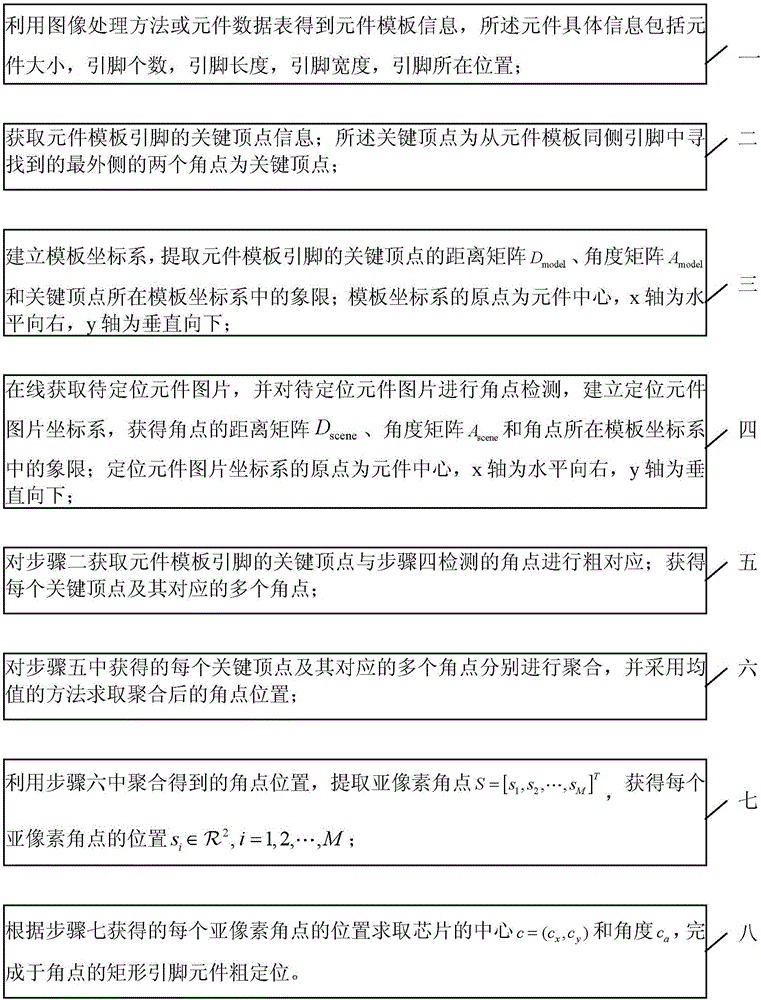
[0018] Step 1, using an image processing method or a component data table to obtain component template information, the component specific information includes component size, pin number, pin length, pin width and pin location;

[0019] Step 2. Obtain the key vertex information of the pin of the component template; the key vertex is the two outermost corner points found from the pin on the same side of the component template as the key vertex;

[0020] Step 3: Establish a template coordinate system and extract the distance matrix D of the key vertices of the component template pins model , angle matrix A model and the quadrant in the template coordinate system where the key vertex is located; the origin of the template coordinate system is...

specific Embodiment approach 2

[0027] Specific embodiment 2. This embodiment is a further description of a corner-based rough positioning method for rectangular pin components described in specific embodiment 1. Step 3 describes the establishment of a template coordinate system and the key to extracting component template pins. Vertex distance matrix D model and the angle matrix A model The specific method is:

[0028] Step 31, according to the key vertices in the component template obtained in step 2, record the quadrant where each key vertex obtained in step 2 is located;

[0029] Step 32: Calculate the distance between different key vertices, the angle between the line between each two key points and the x-axis, and obtain the distance matrix D model and the angle matrix A model The distance matrix D model and the angle matrix A model Both are M×M dimensional matrices; among them, the distance matrix D model and the angle matrix A model The elements in are respectively the distance between the i-t...

specific Embodiment approach 3

[0030] Specific embodiment 3. This embodiment is a further description of a corner-based rough positioning method for rectangular pin components described in specific embodiment 1. In step 4, the online acquisition of the picture of the component to be positioned is obtained, and the picture of the component to be positioned is obtained Carry out corner detection, establish the coordinate system of the component picture, and obtain the distance matrix D of the corner point scene and the angle matrix A scene The method is:

[0031] Step 41, extract corner information, introduce parameter information of component template into corner detection operator, set corner detection window to 2 times minimum pin width;

[0032] Step 42: Take the center of the image of the component to be positioned as the origin, horizontally to the right as the x-axis, and vertically downward as the y-axis; obtain the position of the corner points in the coordinate system and the quadrant where each co...


PUM


Abstract

The invention discloses a rectangular pin element coarse positioning method based on corner points, which belongs to the technical field of image processing, and relates to an element positioning method, and solves the problems that the element positioning algorithm in the existing surface mounting machine is poor in universality, low in execution efficiency and sensitive to lighting. Element template information is obtained by using the image processing method or an element data sheet, a template coordinate system is built, a distance matrix and an angle matrix for key vertexes of the element template pin, and the quadrant of the key vertexes in the template coordinate system are extracted; corner point detection is carried out on a to-be-positioned element picture, and coarse correspondence between the key vertexes and the corner points of the element template pin is carried out; each key vertex and corresponding multiple corner points are acquired; aggregation is carried out on each key vertex and the corresponding multiple corner points, the corner point positions obtained through aggregation are used for extracting subpixel corner points, the center and the angle of a chip are obtained according to the position of each subpixel corner point, and rectangular pin element coarse positioning based on the corner points is completed. The method of the invention is suitable for being used for element positioning.

Description

technical field [0001] The invention belongs to the technical field of image processing and relates to a component positioning method. Background technique [0002] With the rapid development of the electronic information industry, surface mount technology has received great attention. As a key component of surface mount technology, the placement machine plays a vital role in the quality of electronic products. The placement accuracy, efficiency and versatility of the placement machine determine its advanced level. Therefore, higher requirements are put forward for the component positioning algorithm applied to the placement machine. [0003] At present, my country's SMT industry has not yet formed, and there is a large gap with foreign countries. Although some methods about component positioning have been proposed, most of these algorithms focus on using binary images for processing, and the generality and execution efficiency of the algorithms are not high. [0004] Ai...

Claims


Application Information

Patent Timeline
IPC IPC(8): G06T7/70
CPCG06T2207/20164G06T2207/30141
Inventor 高会军杨宪强白立飞孙昊刘鑫许超张智浩
Owner HARBIN INST OF TECH
Why Eureka
Try Eureka