Near-eye display with self-emitting microdisplay engine

A near-eye display, display technology, applied in static indicators, cathode ray tube indicators, instruments, etc., to achieve the effect of increased system compactness and enhanced mechanical robustness

Active Publication Date: 2017-03-08
ICUITI CORP
View PDF13 Cites 14 Cited by
  • Summary
  • Abstract
  • Description
  • Claims
  • Application Information

AI Technical Summary

Problems solved by technology

For these reasons, there is currently no viable microdisplay system that combines diffractive waveguides and s

Method used


Image

  • Near-eye display with self-emitting microdisplay engine
  • Near-eye display with self-emitting microdisplay engine
  • Near-eye display with self-emitting microdisplay engine

Examples


Embodiment Construction

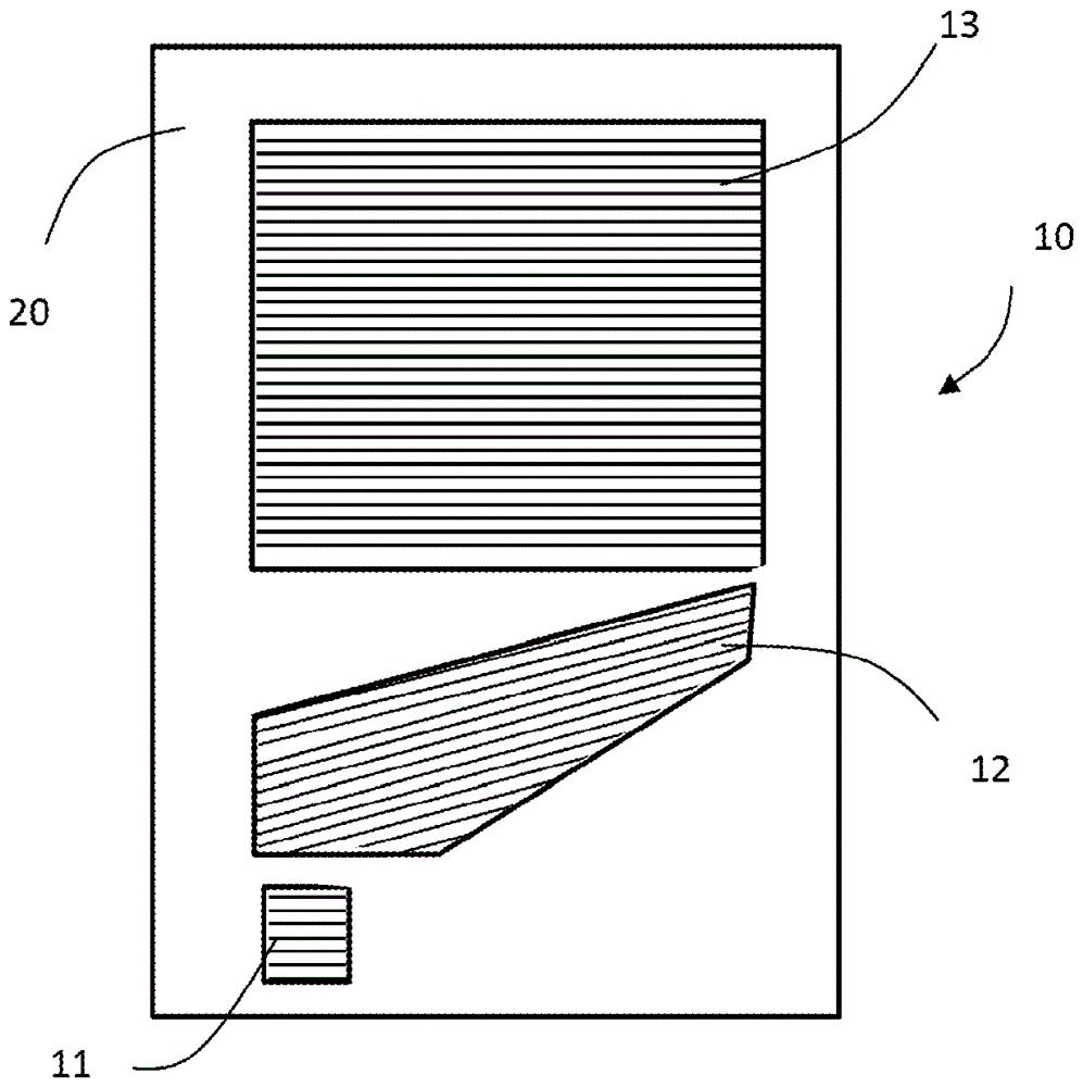
[0027] figure 1 A waveguide 10 is shown comprising an input coupler grating 11 , a 2D pupil expander grating 12 and an outcoupling grating 13 supported by an optically transparent plate-parallel substrate 20 . The gratings 11, 12 and 13 can be replicated on the substrate 20 using a polymer material with a similar refractive index to the substrate, or created as part of the substrate itself. The grating can be patterned using microlithography, holography, stamping and etching methods well known in the art. Although the refractive index of the substrate 10 and gratings 11 up to 13 can be similar to standard glass (eg 1.5), a higher refractive index (such as 1.7) is preferred to maximize the number and angles of modes that can be coupled into the waveguide 10 Maximize range. Both plastic and glass substrates may serve as acceptable substrates as long as the two (front and back) surfaces are highly parallel and sufficiently transmissive to propagate coupled modes without signifi...


PUM


Abstract

A near-eye display for an augmented reality display system couples a self-emitting microdisplay to a transmissive waveguide through an input coupler. Light from the self-emitting microdisplay propagates along the waveguide and through an output coupler for generating a virtual image that is visible together with a real-world scene through the waveguide within an eyebox located in front of the output coupler. A light sensor detects light levels within different portions of the real world scene visible within the eyebox. Drive electronics control the light output from individual pixels of the self-emitting microdisplay to preserve desired local contrast values between the virtual image and the real-world scene.

Description

technical field [0001] The present invention relates to compact display systems, in particular such systems designed to produce magnified virtual images of generated patterns overlaid on real world views produced by microdisplay engines and that can be arranged for use within a head-mounted frame Near-eye viewing or such systems that may be arranged for viewing within the designated exit pupil. Background technique [0002] Augmented reality systems that add computer augmentation to an individual's otherwise unobstructed field of view (FOV) play an important role in applications ranging from enterprise to defense to entertainment. Various attempts have been made to produce portable (wearable) devices, such as eyeglasses or goggles, capable of presenting high-resolution, dynamic digital information within the user's unobstructed field of view of the world. The high dynamic range photon-level environment that the human eye receives with its pupil, lens, and eyelid presents ad...

Claims


Application Information

Patent Timeline
IPC IPC(8): G09G5/10
CPCG06F3/011G02B27/017G02B2027/0178G02B2027/0118G02B2027/014G02B27/0081G09G2320/0626G09G2360/144G02B2027/0138G02B2027/0187G09G2320/066H04N13/332G02B6/0035G02C7/10G02B6/00G02B27/01G02B6/0001G02B6/0016G02B27/0172G06T19/006
Inventor P.J.特拉弗斯
Owner ICUITI CORP
Why Eureka
Try Eureka