Hollow buffer structure for artificial prosthesis
A buffer structure and artificial prosthesis technology, applied in the field of artificial prosthesis, can solve the problems of prosthesis structural rigidity and strength contradiction, strength reduction, etc., and achieve the effect of avoiding reconstruction and loss, increasing mechanical stimulation, and reducing strength
- Summary
- Abstract
- Description
- Claims
- Application Information
AI Technical Summary
Problems solved by technology
Method used
Image
Examples
Embodiment 1
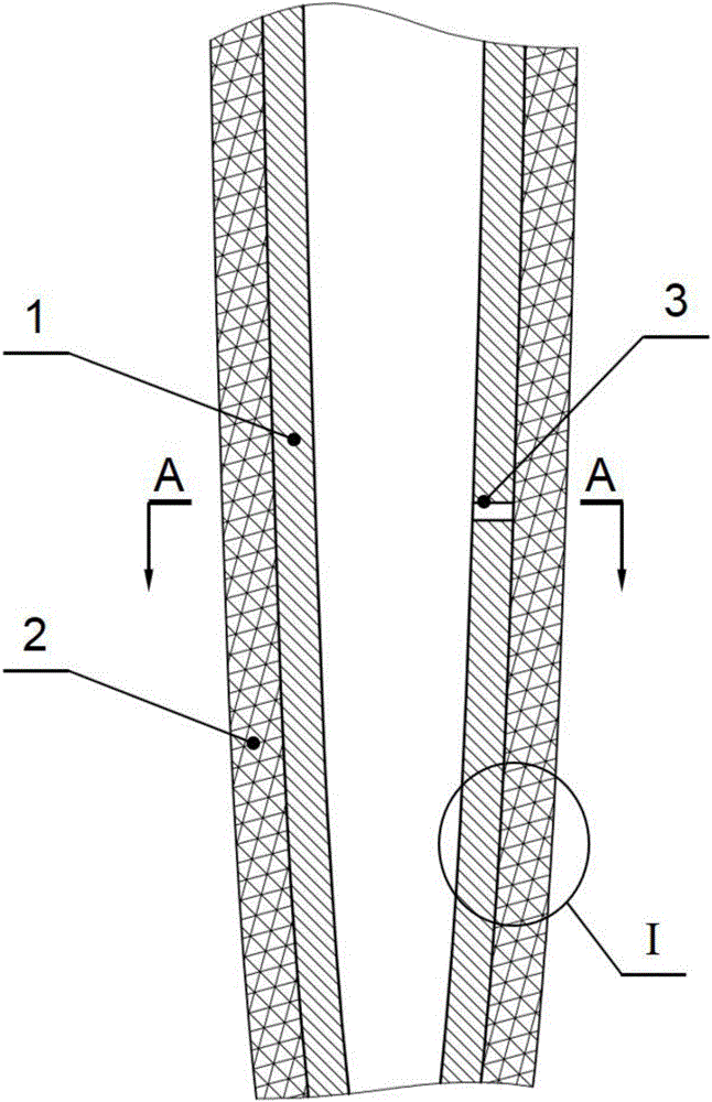
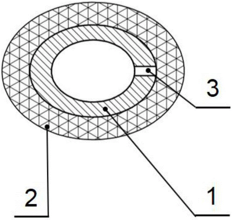
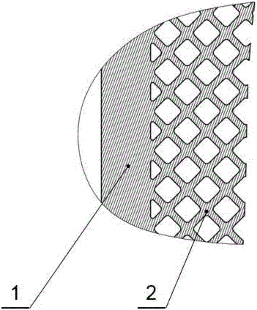
[0035] Embodiment 1, artificial hip joint femoral handle with hollow buffer structure: as Figure 4 with Figure 5 As shown, the artificial hip joint femoral stem mainly includes a neck solid part 4 and a hollow buffer part 5 , wherein the hollow buffer part 5 includes a closed thin-walled part 1 and a buffer structure 2 . The closed thin-walled part 1 is a closed hollow structure, which is located inside the femoral stem of the artificial hip joint and is wrapped by the buffer structure 2; the buffer structure 2 is composed of a three-dimensional grid-like porous structure, which is filled outside the closed thin-walled part 1. The artificial hip joint within the outer contour of the femoral stem. There is a small through hole 3 on the top of the closed thin-walled part 1, the diameter of which is 1mm, and the small through-hole 3 is connected with the positioning hole of the femoral stem of the artificial hip joint to discharge the residual powder inside the closed thin-wal...
Embodiment 2
[0041] Embodiment 2: tibial tray with hollow cushioning structure: as Image 6 with Figure 7 As shown, the tibial tray includes a tray solid part 6 and a hollow buffer part 5 , wherein the hollow buffer part 5 includes a closed thin-walled part 1 and a buffer structure 2 . The closed thin-walled part 1 is a closed hollow structure, which is located at the lower part of the tibial tray and wrapped by the buffer structure 2; the buffer structure 2 is composed of a three-dimensional grid-like porous structure, which is filled outside the closed thin-walled part 1 and inside the outer contour of the tibial tray . There is a small through hole 3 on the top of the closed thin-walled part 1, the diameter of which is 1mm, and the small through hole 3 is located at the center of the bottom of the tibial tray to discharge the residual powder inside the closed thin-walled part 1.
[0042] The shape of the closed thin-walled part 1 of the tibial tray is a body of revolution developed a...
PUM
 Abstract
Description
Claims
Application Information
 - R&D
- Intellectual Property
- Life Sciences
- Materials
- Tech Scout
- Unparalleled Data Quality
- Higher Quality Content
- 60% Fewer Hallucinations
Browse by: Latest US Patents, China's latest patents, Technical Efficacy Thesaurus, Application Domain, Technology Topic, Popular Technical Reports.
© 2025 PatSnap. All rights reserved.Legal|Privacy policy|Modern Slavery Act Transparency Statement|Sitemap|About US| Contact US: help@patsnap.com


