Vacuum-servo and motor hybrid braking system of electric automobile and braking control method

A technology for vacuum boosting and electric vehicles, which is applied in electric vehicles, brake safety systems, brake transmissions, etc., and can solve problems that have not been considered or considered the reliability of a single vacuum sensor, affecting driving safety, etc.

Active Publication Date: 2017-03-15
DONGFENG AUTOMOBILE COMPANY
View PDF8 Cites 9 Cited by
  • Summary
  • Abstract
  • Description
  • Claims
  • Application Information

AI Technical Summary

Problems solved by technology

If the reliability of the vacuum sensor is not high, it is damaged or sends out an error signal—the vacuum degree is insufficient but the vehicle controller is notified that the vacuum degree is sufficient, the vehicle controller fails to order the vacuum pump to work in advance, fails to identify the failure of the vacuum pump in time and reminds the driver to take action Emergency response measures will seriously affect driving safety
[0003] Or the vehicle controller controls the vacuum pump motor to work, hoping to achieve the desired vacuum degree as soon as possible, but because the vacuum pump motor may be mechanically blocked, if the vehicle controller fails to detect it in time and take safety measures, it will seriously affect driving safety
[0004] The patent application number CN201010296300.0 adopts the vacuum pressure sensor signal and the brake pedal signal, and the vacuum pump power supply jointly detects the working condition of the electric vehicle vacuum pump and makes a fault diagnosis, but does not consider the reliability of a single vacuum sensor; the application number is CN201210290307.0 The patent adopts redundant discrimination of vacuum sensor and pressure switch to reduce the impact of a single vacuum switch or false alarm of the vacuum sensor; it is only limited to the alarm after the failure of the vacuum pump part, and does not consider how to take feasible measures after the failure of the vacuum pump sensor or part of the vacuum pump to ensure maximum protection driving safety

Method used


Image

  • Vacuum-servo and motor hybrid braking system of electric automobile and braking control method
  • Vacuum-servo and motor hybrid braking system of electric automobile and braking control method

Examples


Embodiment Construction

[0037] Below in conjunction with accompanying drawing and specific embodiment the present invention is described in further detail:

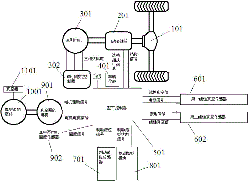
[0038] The electric vehicle vacuum booster and motor composite braking system of the present invention, such as figure 1 As mentioned above, it includes an automatic transmission 201, a traction motor 301, a traction motor controller 302, a vehicle controller 501, a vacuum pump, and a brake pedal module 801. The output shaft of the automatic transmission 201 is used to drive the vehicle drive axle 101, The output shaft of the traction motor 301 is connected to the input shaft of the automatic transmission 201, the three-phase AC output terminal of the traction motor controller 302 is connected to the three-phase AC line input terminal of the traction motor 301, and the CAN communication interface of the traction motor controller 302 is connected to the vehicle control system. The first CAN communication interface of the device 501; the gear sign...


PUM


Abstract

The invention relates to a vacuum-servo and motor hybrid braking system of an electric automobile. The system comprises an automatic gearbox, a traction motor, a traction motor controller, a finished automobile controller, a vacuum pump, a braking pedal module, a braking liquid level sensor, a vacuum pump motor temperature sensor used to monitor temperatures of the vacuum pump, as well as a first linear vacuum sensor and a second linear vacuum sensor installed at an inlet of a vacuum tank, wherein a temperature signal output end of the vacuum pump motor temperature sensor, a linear vacuum signal output end of the first linear vacuum sensor, and a linear vacuum signal output end of the second linear vacuum sensor are connected to an analog acquisition channel of the finished automobile controller; and a braking liquid level signal output end of the braking liquid level sensor is connected to a digital quantity acquisition channel of the finished automobile controller. The system provided by the invention has higher reliability and can effectively avoid safety accidents.

Description

technical field [0001] The invention relates to the technical field of electric vehicle braking safety, in particular to a vacuum booster and motor composite braking system and a braking control method for an electric vehicle. Background technique [0002] The reliability of the vehicle braking system is an important part of vehicle safety. If a traditional small and medium-displacement vehicle is powered by a gasoline engine, it will use the pressure difference between the intake manifold and the atmosphere (that is, the pressure difference between the two sides of the vacuum booster diaphragm) to assist. Push the piston in the brake cylinder to reduce the driver's brake pedal force; electric vehicles usually use an electronic vacuum booster system to amplify the driver's brake pedal force. For the consideration of energy saving and prolonging the life of the vacuum pump (electric vacuum pumps are not suitable for long-term continuous operation), the vacuum pump is usually ...

Claims


Application Information

Patent Timeline
Patent Type & Authority Applications(China)
IPC IPC(8): B60L15/24B60T13/74B60T17/22
CPCB60L15/2009B60L15/24B60L2240/42B60L2260/44B60T13/745B60T17/22Y02T10/72
Inventor 童晓辉周东河朱久艳冯根伍戈小中宫文体
Owner DONGFENG AUTOMOBILE COMPANY
Why Eureka
Try Eureka