
Low-impact non-pyrotechnic separation device

A separation device, non-pyrotechnical technology, which is applied to the docking device of space navigation aircraft, transportation and packaging, space navigation equipment, etc., can solve the problems of malfunction, damage to surrounding parts, inconvenient storage, etc., and achieves small and effective separation impact. Separation, reliable locking effect

Inactive Publication Date: 2017-03-15
SHANGHAI AEROSPACE CONTROL TECH INST
View PDF7 Cites 42 Cited by
  • Summary
  • Abstract
  • Description
  • Claims
  • Application Information

AI Technical Summary

Problems solved by technology

At present, the separation device used in China is basically a pyrotechnic separation device, but the impact it produces is large (3000g ~ 5000g), which can easily lead to damage or malfunction of surrounding components and affect the reliability of separation. It is difficult to apply to precision spacecraft or its accessories. separation
At the same time, the pyrotechnic separation device has shortcomings such as inflammability and explosion, inconvenient storage, transportation and operation, and poor safety in use; it is a one-time consumable and cannot be reused, and its reliability is difficult to verify; a certain proportion of samples must be taken from the same batch of products Do detonation test to verify the batch pass rate, which will inevitably increase the cost

Method used


Image

  • Low-impact non-pyrotechnic separation device
  • Low-impact non-pyrotechnic separation device
  • Low-impact non-pyrotechnic separation device

Examples


Embodiment Construction

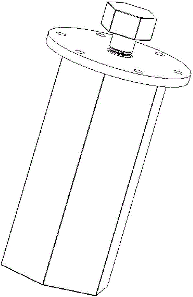
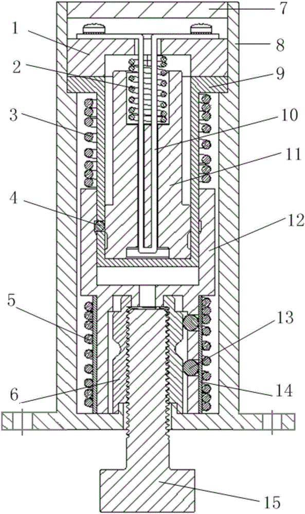
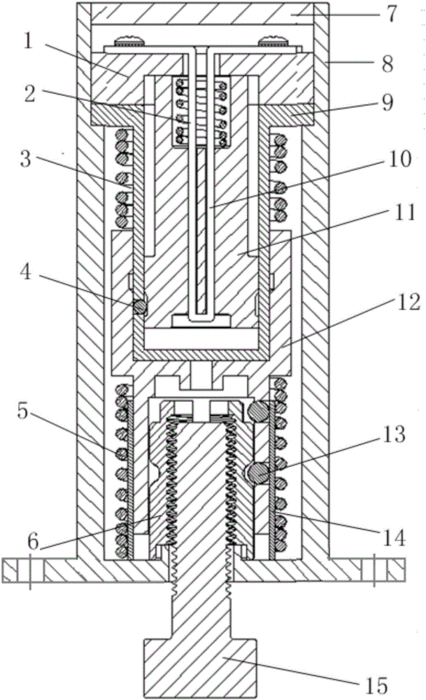
[0019] Such as Figure 1 ~ Figure 2 As shown, the present invention provides a low-impact non-pyrotechnic separation device, which is composed of a shape memory alloy wire 10, a trigger block 11, a split nut 6, a locking sleeve 12, a compression spring 5, a safety spring 2, Buffer spring 3, ball 13, ball retaining ring 14, steel ball 4, shell 8, end cover 7, upper bracket 1, lower bracket 2, the structural composition diagram is as follows figure 2 shown.

[0020] The end of the housing 8 close to the bolt 15 is a flange mounting surface, before the bolt 15 is connected with the non-pyrotechnic separation device, the non-pyrotechnic separation device can be fixed at the place to be installed; the upper bracket 1 is located in the housing 8 and installed on the lower On the bracket 9, a cavity is formed between the upper bracket 1 and the lower bracket 9, and the trigger block 11 is installed in the cavity; after the shape memory alloy wire 10 is folded in half, the folded en...


PUM


Abstract

The invention discloses a low-impact non-pyrotechnic separation device, which is used for the locking and release between stages of a rocket, between a satellite and a launch vehicle, and of a satellite solar panel substrate, an antenna and the like. The low-impact non-pyrotechnic separation device is formed by using a shape memory alloy as a triggering switch and being provided with components and parts of springs, a locking sleeve, a split nut and the like in a matching manner. Based on the shape memory effect of the shape memory alloy, stretching and pre-deformation are firstly carried out on the shape memory alloy during assembly; when separation and unlocking are needed, an alloy material is electrified and heated to be at a phase-transition temperature of the alloy material; the alloy material is recovered to be in a shape before the pre-deformation; thus, a triggering block is driven to act; the locking sleeve is disengaged from the split nut; the release of loads of the satellite and the like is realized. After the one-time separation is completed, a trigger part inside a shell can be conventionally taken out; a shape memory alloy wire is loaded in the low-impact non-pyrotechnic separation device after the pre-deformation is carried out on the shape memory alloy wire once again by adopting a special tool; thus, the low-impact non-pyrotechnic separation device can be repeatedly used. The separation device provided by the invention is low in impact, can be repeatedly used, has no pollution, is low in cost, is safe to use, and is especially applicable to an occasion which is high in the requirement on a separation impact.

Description

technical field [0001] The invention relates to the technical field of spacecraft locking and separation, in particular to a low-impact non-pyrotechnic separation device. Background technique [0002] With the development of micro-nano technology, integrated multi-functional structure, integrated integrated electronics and other technologies, the trend of spacecraft precision is becoming more and more obvious. For example, the development and application of micro-satellites are gradually replacing some space tasks of traditional large satellites. With the improvement of the precision and integration of spacecraft, the separation impact requirements for precision spacecraft like microsatellites are becoming more and more stringent. At present, the separation device used in China is basically a pyrotechnic separation device, but the impact it produces is large (3000g ~ 5000g), which can easily lead to damage or malfunction of surrounding components and affect the reliability o...

Claims


Application Information

Patent Timeline
IPC IPC(8): B64G1/64
CPCB64G1/645
Inventor 冯伟冀娟傅俊勇曾凡铨胡翔宇
Owner SHANGHAI AEROSPACE CONTROL TECH INST
Learn More