Fall-proof U-shaped foot pin for iron tower and use method thereof

A foot nail and U-shaped technology, applied in the field of tower climbing equipment, can solve the problems of human body hanging, poke injury, inconvenient installation and maintenance, complicated installation and layout, etc. Effect

Active Publication Date: 2017-03-15
GUIYANG POWER SUPPLY BUREAU OF GUIZHOU POWER GRID CO LTD
View PDF5 Cites 2 Cited by
  • Summary
  • Abstract
  • Description
  • Claims
  • Application Information

AI Technical Summary

Problems solved by technology

When a person falls from the tower, the fixed seat belt and the human body form a single pendulum effect, and the hook and cone shape of the foot nails will cause hanging and poking damage to the human body
In addition, there are also some areas that use the combination of rail-type climbing and falling protectors, anti-fall guide rails and full-body seat belts. Although the safety has been effectively improved, it is difficult to popularize because of its high production cost and complicated installation arrangements.
Chinese patent application (CN201137458Y) discloses a U-shaped foot nail for preventing falling of an iron tower. The two ends of the open end of the foot nail are connected to the steel frame of the iron tower with threads. For matching, the footnail used on the existing traditional iron tower is a steel bar, which is connected to the steel frame through one end of the footnail thread. It needs to drill another hole to meet the installation of U-shaped footnails, and the transformation is complicated. Inconvenient installation and maintenance

Method used


Image

  • Fall-proof U-shaped foot pin for iron tower and use method thereof
  • Fall-proof U-shaped foot pin for iron tower and use method thereof
  • Fall-proof U-shaped foot pin for iron tower and use method thereof

Examples


Embodiment

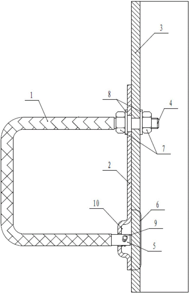
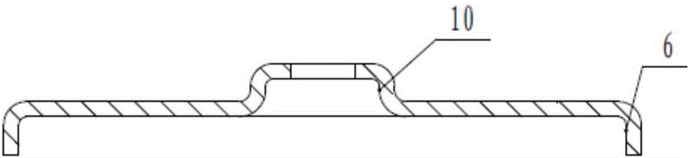
[0037] Example: such as Figure 1-Figure 4 As shown, a U-shaped foot nail for preventing falling of an iron tower includes a U-shaped foot nail 1 and a limiting plate 2. The U-shaped foot nail 1 is arranged on the steel frame 3 of the iron tower, and the end-4 of the open end is connected to the steel frame. 3 is fixedly connected, the end two 5 of the opening end is connected with the lower part of the limiting plate 2, and the two ends are arranged vertically, the upper part of the limiting plate 2 passes through the end one 4 and is tightly connected to the steel frame 3, and the lower part is back The side is provided with a limit groove 6 that is engaged with the steel frame 3 .

[0038] Preferably, the above-mentioned end part one 4 penetrates into the wall plate of the steel frame 3 and fastens the wall plate of the steel frame 3 and the limit plate 2 through double nuts 7, which is convenient and fast for loading and unloading, and the connection is reliable.

[0039]...

Embodiment 2

[0044] Embodiment 2: a kind of use method of the U-shaped foot nail of iron tower anti-falling, this method comprises the following steps:

[0045] (1) Install U-shaped foot nails on the D leg of the right main material of the tower, starting from about 1.5 meters above the foundation top plane to 0.5 meters from the top of the tower, and alternately installing them on both sides of a right-angle steel of the main material, each The horizontal and vertical spacing between the lower sides of two adjacent sets of spikes is 0.45 meters;

[0046] (2) Use the safety belt hook of the fall arrester to hook into the frame formed by the U-shaped spikes, select one side from the three-frame portion formed by the spikes with bare hands, and hold the spikes firmly, and step firmly in the frame formed by the spikes , rely on the strength of the arms and legs to move the body, and use the hooks on the left and right sides of the safety belt to climb;

[0047] (3) Until climbing to the desi...

Embodiment 3

[0048] Embodiment 3: a kind of use method of the U-shaped foot nail of iron tower fall prevention, this method comprises the following steps:

[0049] (1) Remove the traditional single cylindrical iron tower foot nail;

[0050] (2) Put the upper threaded open end of the U-shaped foot nail into the nut and washer;

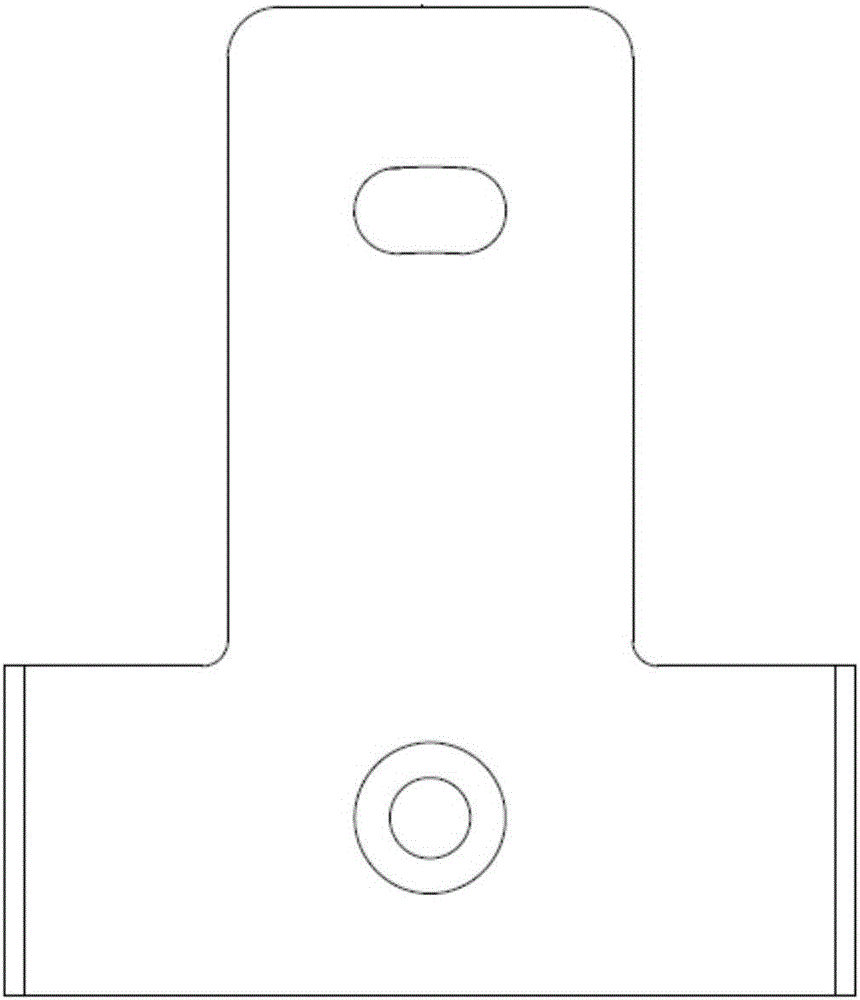
[0051] (3) Pass the upper through hole of the steel limiting plate through the upper opening end of the U-shaped foot nail. The upper through hole is the diameter of the U-shaped foot nail + 0.5mm, and make right-angle folds at 50mm downwards on both sides of the limiting plate. Bend to form a limit groove, the limit groove is used to clamp the main material angle steel of the iron tower;

[0052] (4) The lower side of the limit plate is provided with a convex shape, that is, a groove on the back, and a limit hole is set on the convex shape. The limit hole is a U-shaped nail diameter + 0.5mm, and the convex shape protrudes from the front surface of the limit plate ...


PUM


Abstract

The invention discloses a fall-proof U-shaped foot pin for an iron tower and a use method thereof. The fall-proof U-shaped foot pin for the iron tower comprises a U-shape foot pin and a limiting plate, wherein the U-shape foot pin is arranged on a steel frame of the iron tower, end 1 of an open end of the U-shaped foot pin is fixedly connected with the steel frame, end 2 of the open end of the U-shaped foot pin is connected with the lower portion of the limiting plate, the two ends of the open end of the U-shaped foot pin are vertically arranged, the upper portion of the limiting plate passes through the end 1, and fixedly connected with the steel frame together with the end 1 in close mode, and a limiting groove clamped on the steel frame is formed in the back side of the lower portion of the limiting plate. By using the U-shaped foot pin and the limiting plate, the fall-proof U-shaped foot pin for the iron tower can be conveniently and quickly installed on the steel frame, saves a process of manufacturing holes in the steel frame, and is convenient to assemble and unassembled and maintain. Especially for remolding of a traditional reinforcing steel bar foot pin, an existing installation through hole is used, and then the limiting plate and the U-shaped foot pin can be conveniently and quickly installed on the steel frame of the iron tower, remolding is easy, shinning safety of the traditional iron tower and reliability of the foot pin are greatly improved, remolding cost is low, and the fall-proof U-shaped foot pin for the iron tower further has the advantages of being simple in structure and low in cost.

Description

technical field [0001] The invention relates to a U-shaped foot nail for preventing falling of an iron tower and a using method thereof, belonging to the technical field of iron tower climbing equipment. Background technique [0002] At present, the iron towers of the power transmission lines are all equipped with foot spikes for climbing, which are cylindrical steel bars in a shape. There are no protective measures on the side of the spikes, so that climbers often have accidents due to side slipping of the feet; when the staff climbs up and down the iron tower or shifts the operation on the tower, if the used safety belt hook is buckled Hanging on the spikes will also lose the protective effect due to side slipping and falling out; in addition, the surface of the existing spikes is relatively smooth, and climbers tend to slip when stepping hard, resulting in loose grip and falling towers, and Only one end of the foot nail is connected to the iron tower. After being subject...

Claims


Application Information

Patent Timeline
Patent Type & Authority Applications(China)
IPC IPC(8): E06C9/04
CPCE06C9/04
Inventor 杨杰
Owner GUIYANG POWER SUPPLY BUREAU OF GUIZHOU POWER GRID CO LTD
Why Eureka
Try Eureka