Valve guide pipe

A technology of valve guides and guides, which is applied in the direction of lift valves, lubrication of valve accessories, engine components, etc. It can solve the problems of reduced service life of general gasoline engines, poor internal lubrication of valve guides, and reduced service life, so as to prevent excessive gaps, Reduce oil consumption and improve emissions

Inactive Publication Date: 2017-03-15
YIZHENG CHANGDA POWDER METALLURGY PROD CO LTD
View PDF0 Cites 2 Cited by
  • Summary
  • Abstract
  • Description
  • Claims
  • Application Information

AI Technical Summary

Problems solved by technology

[0003] The cylinder head of the existing general-purpose gasoline engine is equipped with a straight-tube-shaped valve guide, and there is a problem that oil leaks into the combustion chamber of the cylinder head through the outer wall of the valve guide, causing a large amount of carbon deposits, increasing the working temperature, and reducing the service life of the general-purpose gasoline engine; The internal oil storage is too small, and the oil volume gradually decreases with the movement of the valve, so the lubrication of the guide rod and the inner wall of the valve guide cannot be guaranteed for a long time. Because the temperature of the lower part of the valve guide is too high, the internal lubrication of the valve guide is worse, causing The surface damage of the guide rod and the inner wall of the valve guide will reduce the service life of both

Method used


Image

  • Valve guide pipe

Examples


Embodiment Construction

[0017] In order to make the content of the present invention clearer and easier to understand, the content of the present invention will be further described below in conjunction with the accompanying drawings. Of course, the present invention is not limited to this specific embodiment, and general replacements known to those skilled in the art are also covered within the protection scope of the present invention. Secondly, the present invention is described in detail by means of schematic diagrams. When describing the examples of the present invention in detail, for the convenience of explanation, the schematic diagrams are not partially enlarged according to the general scale, which should not be used as a limitation of the present invention.

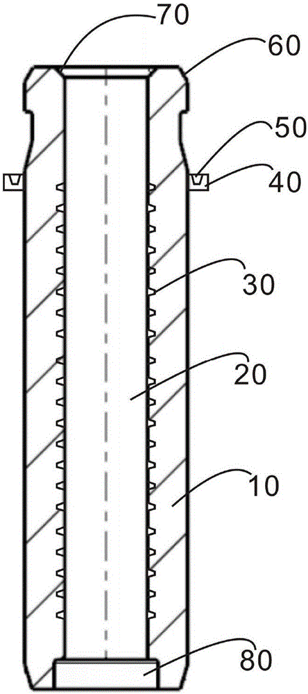
[0018] The above and other technical features and beneficial effects will be described in detail on the valve guide of the present invention in conjunction with the embodiments and the accompanying drawings. figure 1 It is a structura...


PUM


Abstract

The invention relates to a valve guide pipe. The valve guide pipe comprises a guide pipe body, wherein a through hole is arranged in the guide pipe body along the axial direction of the guide pipe body; a plurality of oil storage grooves are arranged in the surface of the through hole; a boss is arranged on the outer surface of the guide pipe body; an oil injection port is arranged in the boss and communicates with an oil storage groove; externally tangential surfaces are arranged on the outer walls of ports in the two ends of the guide pipe body; an internally tangential surface is arranged on the inner wall of the port in one end of the guide pipe body; and a groove structure is arranged on the inner wall of the other port. According to the valve guide pipe disclosed by the invention, lubricant oil is input in the oil storage groove through the oil injection port, thus wear of a valve rod due to insufficient lubrication with the valve guide pipe during cold start is reduced; meanwhile, a part of the lubricant oil can be stored on an inner cutting surface, thus formation of oil film lubrication between the valve guide pipe and the valve rod is benefited, and conduction of heat to a cylinder cover from the valve rod through the valve guide pipe is facilitated; and in addition, a sharp corner generated by the inner wall of the groove structure has a scraping function, and coking and carbon deposition already formed by the valve rod and the valve guide pipe part are removed and prevented from entering the valve guide pipe.

Description

technical field [0001] The invention relates to a valve assembly, in particular to a valve guide. Background technique [0002] At present, the valves used in automobiles are composed of two parts: the valve head and the valve stem. Most of the valve guides are cylindrical structures with through holes, which are set on the valve stem and keep a small fit gap with the valve stem to reduce wear. , The function of the valve guide is to guide the movement of the valve, to ensure the linear reciprocating motion of the valve, so that the valve and the valve seat or valve seat ring can be properly fitted, and in addition, the heat received by the valve stem is partially transferred to the cylinder head. [0003] The cylinder head of the existing general-purpose gasoline engine is equipped with a straight-tube-shaped valve guide, and there is a problem that oil leaks into the combustion chamber of the cylinder head through the outer wall of the valve guide, causing a large amount o...

Claims


Application Information

Patent Timeline
IPC IPC(8): F01L3/08F01M9/10
CPCF01L3/08F01M9/10F01M9/106
Inventor 周学斌
Owner YIZHENG CHANGDA POWDER METALLURGY PROD CO LTD
Why Eureka
Try Eureka