
Self-calibration and compensation method for framework nonorthogonal angle of triaxial rotating inertial navigation syste

An inertial navigation system, three-axis rotation technology, applied in the direction of measuring devices, instruments, etc., can solve the research on non-orthogonal angle calibration of the rotating inertial navigation frame is rare, reduce the attitude output accuracy of the rotating inertial navigation system, and the attitude output of the rotating inertial navigation system Accuracy drop and other issues

Active Publication Date: 2017-03-15
BEIHANG UNIV
View PDF5 Cites 9 Cited by
  • Summary
  • Abstract
  • Description
  • Claims
  • Application Information

AI Technical Summary

Problems solved by technology

[0003] In the current research on the rotary inertial navigation system, a large number of literatures show that the rotary inertial navigation system can improve the position and velocity accuracy by about an order of magnitude; but in the actual use process, the attitude output accuracy of the rotary inertial navigation system may decrease
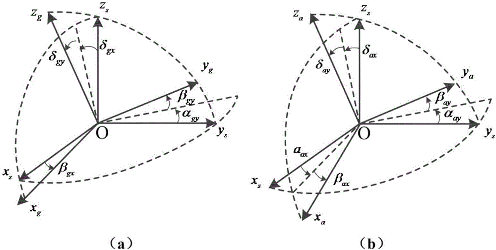
In the three-axis rotary inertial navigation system, the machining and equipment errors of the frame lead to the existence of non-orthogonal angles between the frames, which will reduce the attitude output accuracy of the rotary inertial navigation system
In the existing literature, there are few studies on the non-orthogonal angle calibration of the rotating inertial navigation frame

Method used


Image

  • Self-calibration and compensation method for framework nonorthogonal angle of triaxial rotating inertial navigation syste
  • Self-calibration and compensation method for framework nonorthogonal angle of triaxial rotating inertial navigation syste
  • Self-calibration and compensation method for framework nonorthogonal angle of triaxial rotating inertial navigation syste

Examples


Embodiment Construction

[0079] The present invention will be further described below in conjunction with the accompanying drawings.

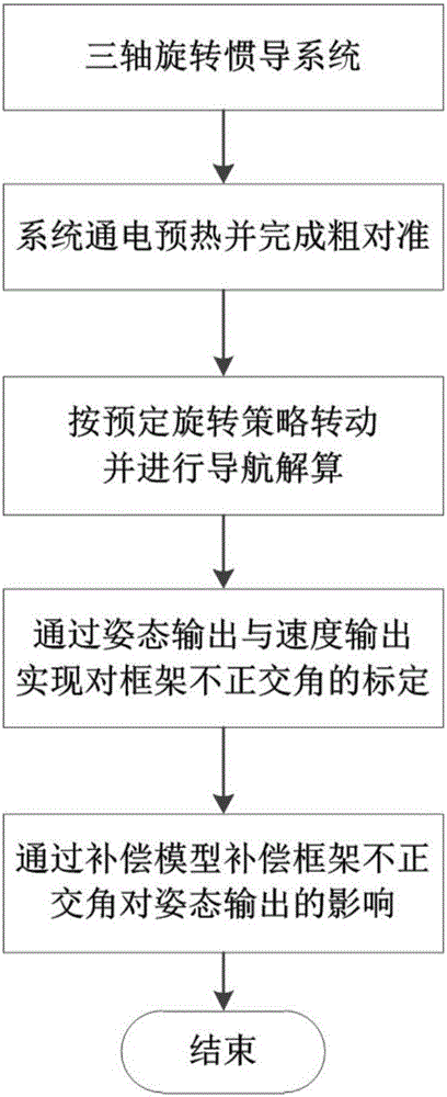
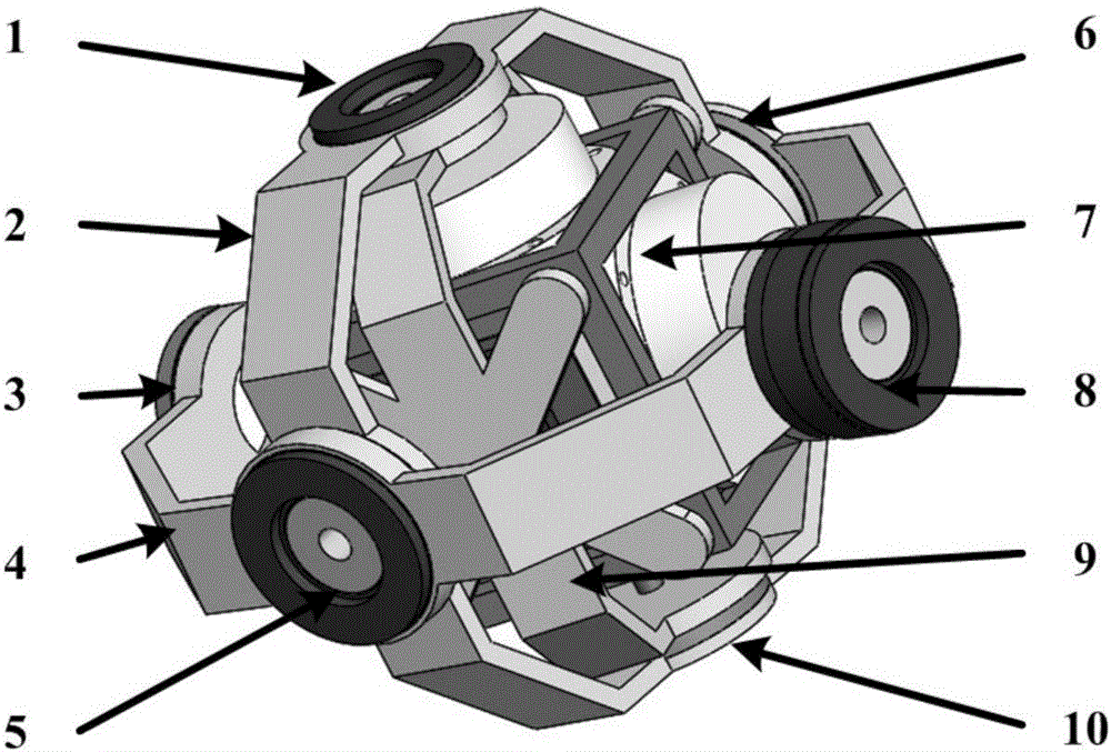
[0080] figure 1 The flow chart of the implementation of the non-orthogonal angle self-calibration and compensation method for the frame of the three-axis rotary inertial navigation system of the present invention is given. The main steps of the method are: the three-axis rotary inertial navigation system is powered on for preheating and rough alignment is completed; the three-axis rotary inertial navigation system controls the rotation of the frame according to a predetermined selection strategy and performs navigation calculation at the same time; records the attitude output during the navigation process With the speed output, the calibration of the non-orthogonal angle of the three-axis rotary inertial navigation system frame is realized through the recursive least square algorithm; the influence of the non-orthogonal angle of the frame on the attitude output of the...


PUM


Abstract

The invention discloses a self-calibration and compensation method for a framework nonorthogonal angle of a triaxial rotating inertial navigation system. The method includes the following steps that the triaxial rotating inertial navigation system is powered on to be preheated, and coarse alignment is completed; the triaxial rotating inertial navigation system controls a framework to rotate according to a preset selection strategy and carries out navigation solution at the same time; posture output and speed output in the navigation process are recorded, and a recursive least-square method is used for calibrating the framework nonorthogonal angle of the triaxial rotating inertial navigation system; influence on the posture output of the triaxial rotating inertial navigation system is compensated through a compensation model. The calibration method for the framework nonorthogonal angle of the triaxial rotating inertial navigation system is simple in process, high in calibration precision and capable of achieving self-calibration of the framework nonorthogonal angle without machine disassembling and facilitates engineering implementation. The compensation algorithm of the framework nonorthogonal angle is easy to implement, and the precision of posture output of the triaxial rotating inertial navigation system is remarkably improved after compensation.

Description

technical field [0001] The invention relates to a self-calibration and compensation method for the non-orthogonal angle of the frame of a three-axis rotary inertial navigation system, belongs to the technical field of calibration of the non-orthogonal angle of the frame of the rotary inertial navigation system, and is suitable for self-calibration and compensation of the non-orthogonal angle of the frame of the three-axis rotary inertial navigation system , especially suitable for applications that require the rotary inertial navigation system to achieve non-orthogonal angle calibration of the frame without dismantling the machine. Background technique [0002] The inertial navigation system forms an inertial measurement unit (InertialMeasurement Unit, IMU) through three gyroscopes and three accelerometers installed orthogonally to measure the angular velocity and acceleration of the carrier relative to the inertial space, and gives the real-time position of the carrier based...

Claims


Application Information

Patent Timeline
IPC IPC(8): G01C25/00
CPCG01C25/005
Inventor 李魁高鹏宇王蕾宋天骁
Owner BEIHANG UNIV
Learn More