Emissivity calibration method for infrared temperature measurement system

A technology of infrared temperature measurement and calibration method, which is applied in the field of infrared temperature measurement, can solve the problems that the emissivity of objects is prone to errors, affect the temperature measurement accuracy, and increase the hardware configuration, so as to overcome the defects of emissivity correction, increase power consumption, simple method effect

Inactive Publication Date: 2017-03-15
JING LIN CHENGDU SCI & TECH
View PDF4 Cites 12 Cited by
  • Summary
  • Abstract
  • Description
  • Claims
  • Application Information

AI Technical Summary

Problems solved by technology

Since the emissivity is affected by the wavelength, temperature, and surface characteristics of the object, the emissivity of the object is prone to errors, which affects the temperature measurement accuracy
At present, there are two ways to avoid emissivity error. One is to manually adjust the emissivity parameters. This method often needs to learn from experience information, so errors will still be introduced; Temperature measurement and parallel equations are used to solve the emissivity, effectively avoiding the shortcomings caused by artificial settings, but this method will increase the hardware configuration; therefore, it is necessary to study how to accurately and easily correct the emissivity

Method used


Image

  • Emissivity calibration method for infrared temperature measurement system
  • Emissivity calibration method for infrared temperature measurement system
  • Emissivity calibration method for infrared temperature measurement system

Examples


Embodiment Construction

[0036] The technical solution of the present invention will be further described in detail below in conjunction with the accompanying drawings, but the protection scope of the present invention is not limited to the following description.

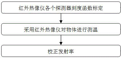
[0037] like figure 1 As shown, the emissivity calibration method for the infrared temperature measurement system includes the following steps:

[0038] S1: Use a temperature-controllable black body to calibrate the calibration functions of each detector of the infrared thermal imager at close range;

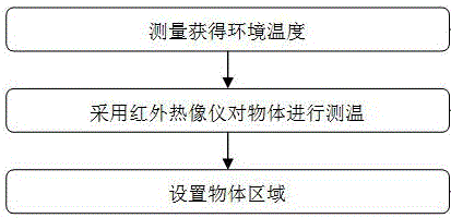
[0039] S2: Use an infrared thermal imager to measure the temperature of the object;

[0040] S3: Correct the emissivity.

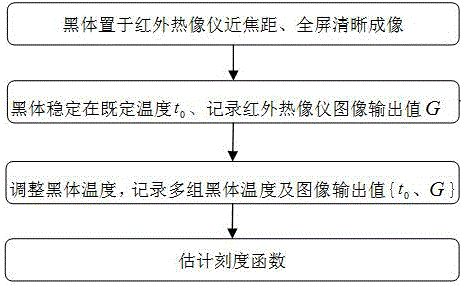
[0041] like figure 2 As shown, the calibration of the detector calibration function in the step S1 specifically includes the following steps:

[0042] S11: The black body is placed in the clear imaging place of the infrared thermal imager near the focal length, and the black body is filled with the image screen. The b...


PUM


Abstract

The invention discloses an emissivity calibration method for an infrared temperature measurement system. The method comprises the following steps that: (1), a black body with a controllable temperature is used for calibrating scale functions of all detectors of a thermal infrared imager at a short distance; (2), the thermal infrared imager is used for measuring the temperature of an object; and (3), according to a temperature measurement result and the scale function expression coefficient, an error objective function related to an emissivity is constructed and the objective function is solved to realize emissivity correction. According to the apparent temperature obtained by the thermal infrared imager, the scale functions of all detectors, and the environment temperature, the emissivity of the target object is corrected by using an airspace technology, thereby overcoming defects of existing emissivity correction. Moreover, the method is simple and is easy to implement; no more hardware module needs to be added; and no more power consumption is caused.

Description

technical field [0001] The invention relates to the field of infrared temperature measurement, in particular to an emissivity calibration method for an infrared temperature measurement system. Background technique [0002] The infrared thermal imager uses the infrared detector and the optical imaging objective lens to receive the infrared radiation energy distribution pattern of the measured target and reflect it on the photosensitive element or thermal element of the infrared detector to obtain an infrared thermal image. Corresponds to the heat distribution field on the surface of the object. In layman's terms, an infrared thermal imager converts the invisible infrared energy emitted by an object into a visible thermal image. Different colors on the top of the thermal image represent different temperatures of the measured object. [0003] Emissivity is an important parameter of the infrared temperature measurement system, which can be used to solve the surface temperature...

Claims


Application Information

Patent Timeline
IPC IPC(8): G01J5/00
CPCG01J5/00G01J2005/0077G01J5/802
Inventor 路璐
Owner JING LIN CHENGDU SCI & TECH
Why Eureka
Try Eureka