
Multispectral fusion imaging lens and applications

An imaging lens, multi-spectral technology, applied in optics, optical components, instruments, etc., can solve the problems of low optical path intensity, mutual interference, difficult reception, etc., to achieve high image accuracy, reduced lens volume, and reduced light energy. Effect

Inactive Publication Date: 2017-03-15
YUNNAN KIRO CH PHOTONICS +1
View PDF6 Cites 14 Cited by
  • Summary
  • Abstract
  • Description
  • Claims
  • Application Information

AI Technical Summary

Problems solved by technology

[0003] Although the traditional structure of using a spectroscope to split light can achieve the purpose of splitting light, due to multiple reflections and transmissions, coupled with the influence of mutual interference, the intensity of the light path after splitting is low, and it is difficult to receive and form a clear and accurate output image
The Chinese patent application with the publication number CN 105572866 discloses a visible light and infrared composite imaging device, which uses a reflector to reflect visible light out of the optical path, respectively receives visible light and infrared light and then fuses them. It is an idea of ​​infrared and visible light fusion, but cannot Solve the problem that the energy reduction of infrared light is difficult to detect after transmission; the infrared detector needs higher energy to detect infrared light, which requires that the infrared energy should not be lost too much, and the energy required by the infrared detectors of different wavelengths is different. There are differences between cooling and uncooling; compared with infrared detectors, visible light detectors require less energy for detection; at the same time, from the perspective of cost and lens size, in order to avoid the interference of the separated optical paths, it is necessary to lengthen the distance between the lenses. The distance increases the lens at the same time, so the use of light splitting structure often results in too large lens and high cost

Method used


Image

  • Multispectral fusion imaging lens and applications
  • Multispectral fusion imaging lens and applications
  • Multispectral fusion imaging lens and applications

Examples


Embodiment 1

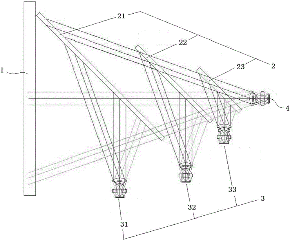
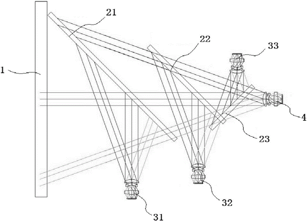
[0032] Such as figure 1 As shown, a multi-spectral infrared and visible light compound imaging lens, including:

[0033] The window lens 1 is placed at the front end of the lens with a sapphire lens to ensure the transmission of infrared and visible light.

[0034] The beam splitter 2 includes the first beam splitter 21, the second beam splitter 22, and the third beam splitter 23. The surface types of the three beam splitters are all flat, forming an angle of 45° with the window lens, and the three beam splitters are parallel to each other.

[0035] The first beam splitter 21 has the largest lens size, which is related to the actual demand and the size of the window lens. It is made of sapphire material, reflects long-wave infrared, and transmits medium-wave, short-wave infrared and visible light;

[0036] The lens size of the second beam splitter 22 is reduced compared to the first beam splitter 21, and adopts ZnSe material to reflect mid-wave infrared and transmit short-wa...

Embodiment 2

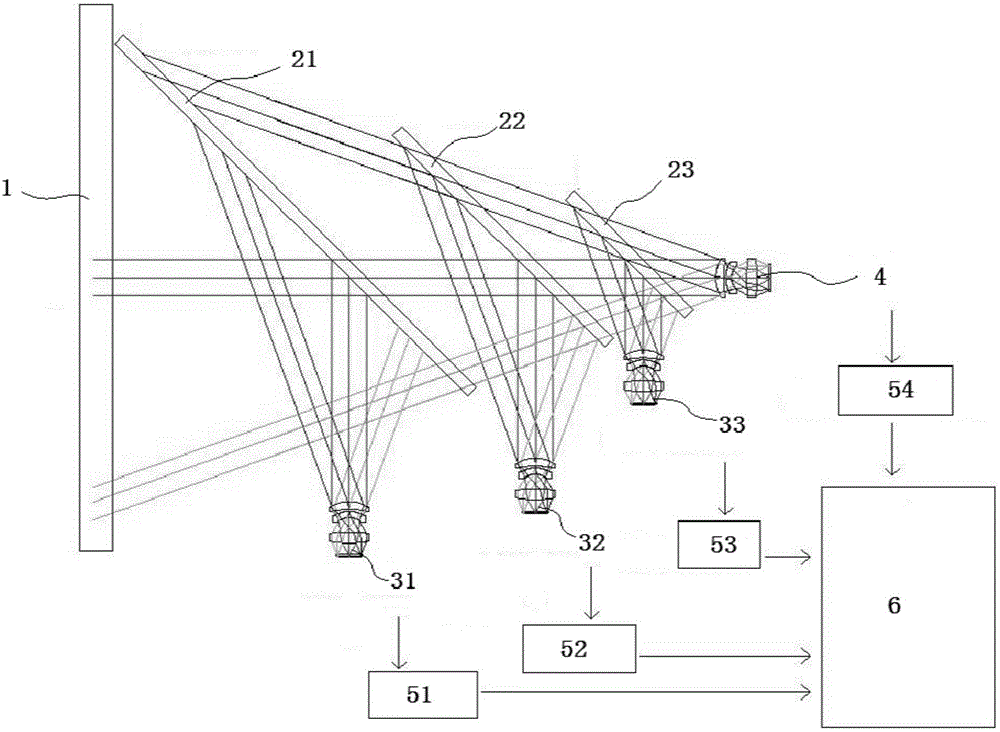
[0043] Such as image 3 As shown, a multispectral fusion optical system includes: the multispectral fusion imaging lens, detector group and image fusion output system 6 provided in embodiment 1, the multispectral fusion imaging lens is connected with the detector group, and the detector group is connected with the image The fusion output system is connected, and the detector group includes a long-wave infrared uncooled detector 51, a mid-wave infrared cooled detector 52, a short-wave infrared detector 53 and a visible light detector 54;

[0044] The long-wave detector 51 is connected to the long-wave objective lens group by using an uncooled long-wave detector, and connected to the long-wave infrared light objective lens group to detect long-wave infrared light;

[0045]The medium-wave detector 52 adopts a cooling-type medium-wave detector to connect to the medium-wave objective lens group and to the medium-wave infrared objective lens group to detect medium-wave infrared ligh...


PUM


Abstract

The invention discloses a multispectral fusion imaging lens and applications. The imaging lens comprises a window lens (1), a beam splitter group (2), an infrared objective lens group (3) and a visible light objective lens group (4), wherein the beam splitter group (2) comprises a first beam splitter (21), a second beam splitter (22) and a third beam splitter (23), and the three beam splitters are mutually parallel and are all located on an optical path for sequentially splitting infrared light with a long wavelength, a middle wavelength and a short wavelength out of the optical axis; the infrared objective lens group (3) comprises a long-wavelength infrared objective lens group (31), a middle-wavelength infrared objective lens group (32) and a short-wavelength infrared objective lens group (33), and the three objective lens groups are all vertical to the optical path for receiving the split infrared light with different wavelengths one by one; and the visible light objective lens group (4) is located at the tail end of the optical path. The spectral fusion imaging lens provided by the invention can fuse infrared images of different bands and the invisible image, the structure is simple, the light utilization efficiency is high, and the image accuracy is high after beam splitting fusion.

Description

technical field [0001] The invention belongs to the technical field of optical imaging, in particular to a multi-spectral fusion imaging lens and its application. Background technique [0002] Infrared images of different bands have different advantages in describing objects and environments, while the advantage of visible light images is that they are clearly visible to the naked eye. The existing technology often fuses a single-band infrared image with a visible light image, which has certain limitations in its adaptability to the environment and the accuracy of the image. However, the fusion of visible light images with long-wave, medium-wave, and short-wave infrared images can Improve the adaptability of the optical system to the environment, so as to obtain more reliable and accurate image information. [0003] Although the traditional structure of using a spectroscope to split light can achieve the purpose of splitting light, due to multiple reflections and transmissi...

Claims


Application Information

Patent Timeline
IPC IPC(8): G02B27/10
CPCG02B27/1013G02B27/1006
Inventor 刘福平金伟其陈骥张力元张旭罗永芳李洪兵王彩萍
Owner YUNNAN KIRO CH PHOTONICS
Learn More