
Graphical substrate for LED chip and preparation method of graphical substrate

A LED chip and graphic technology, applied in the direction of electrical components, electrical solid devices, circuits, etc., can solve the problems of unfavorable integrated application, unfavorable light extraction efficiency, large system volume, etc., to facilitate integrated application, reduce series thermal resistance, improve The effect of light extraction efficiency

Inactive Publication Date: 2017-03-15
INST OF SEMICONDUCTORS - CHINESE ACAD OF SCI +1
View PDF6 Cites 2 Cited by
  • Summary
  • Abstract
  • Description
  • Claims
  • Application Information

AI Technical Summary

Problems solved by technology

Whether it is a bracket or a substrate, its configuration is generally a planar structure, which causes the part of the light emitted from the end surface of the epitaxial layer of the LED chip to be easily absorbed by the electrodes on the substrate, packaging materials or brackets, which is not conducive to the maximum light extraction efficiency. The substrate of the LED chip is thicker, which also makes the system larger, which is not conducive to integrated applications

Method used


Image

  • Graphical substrate for LED chip and preparation method of graphical substrate
  • Graphical substrate for LED chip and preparation method of graphical substrate
  • Graphical substrate for LED chip and preparation method of graphical substrate

Examples


Embodiment Construction

[0044] In order to make the objectives, technical solutions and advantages of the present invention clearer, the present invention will be further described in detail below in conjunction with specific embodiments and with reference to the accompanying drawings.

[0045] The specific embodiment 1 of the present invention will be described in detail below with reference to the accompanying drawings to make the advantages and features of the present invention easier to understand by those skilled in the art, so as to make a clearer and clearer definition of the protection scope of the present invention.

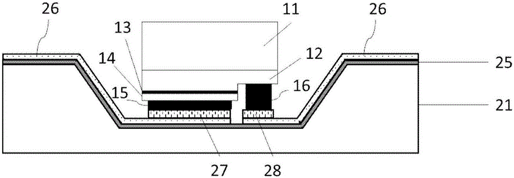
[0046] Such as figure 1 This is a schematic cross-sectional view of the LED flip chip in specific embodiment 1 of the present invention. It is a type of semiconductor structure, including 11 is a substrate; 12 is an n-type layer; 13 is an active area; 14 is a p-type layer; p-type electrode; 16 is an n-type electrode. The patterned substrate provided by the present invention can be c...


PUM


Abstract

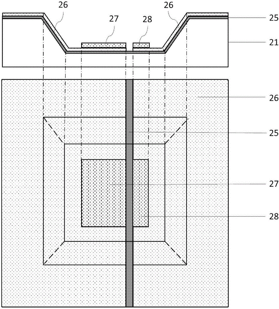
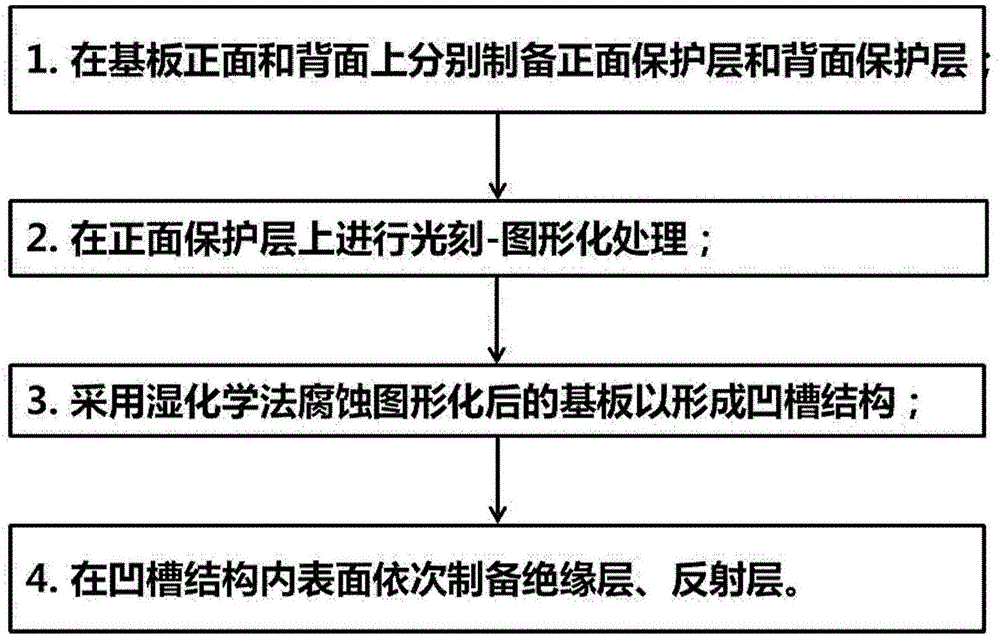
The invention discloses a graphical substrate for an LED chip and a preparation method of the graphical substrate, and relates to the technical field of semiconductor packaging. In order to effectively utilize light emitted from the end surface of an epitaxial layer of the LED chip, the invention provides the graphical substrate used for the LED chip. The graphical substrate comprises a groove structure which is used for changing the propagation direction of the light emitted from the end surface of the LED chip at a short distance, so that the light loss is reduced and the light-extraction efficiency of the LED chip is greatly improved. Meanwhile, the thickness of the substrate is reduced, the serial thermal resistance of a system is reduced; the volume of a packaging module can be greatly reduced; and integrated application is facilitated. In addition, the invention provides the preparation method of the graphical substrate. The substrate is corroded through a wet process to obtain the graphical substrate with the groove structure.

Description

Technical field [0001] The invention relates to the field of semiconductor packaging, in particular to a patterned substrate of an LED chip and a preparation method thereof. Background technique [0002] Since the 1990s, LEDs have attracted widespread attention and have developed rapidly. For example, GaN-based LEDs have wavelengths covering green and ultraviolet wavelengths, and have significant advantages such as low energy consumption, long life, and fast response time. Visible light communication, polymer curing, sterilization and disinfection have huge market value or potential application value. [0003] LEDs usually epitaxial semiconductor layers such as n-type layer, light-emitting area (ie active area) and p-type layer on a homogeneous or heterogeneous substrate in sequence. These semiconductor layers have a high refractive index. For example, the refractive index of GaN material in the visible light band is 2.3-2.4, which is far from the refractive index of air (n=1). T...

Claims


Application Information

Patent Timeline
Patent Type & Authority Applications(China)
IPC IPC(8): H01L33/00H01L33/22H01L33/48H01L33/60
CPCH01L2224/16225H01L33/22H01L33/0054H01L33/48H01L33/60H01L2933/005H01L2933/0058
Inventor 张韵郭亚楠曹峻松王军喜李晋闽
Owner INST OF SEMICONDUCTORS - CHINESE ACAD OF SCI
Learn More