Optical module and optical signal receiving circuit

A technology for receiving circuits and optical signals, which is applied in the field of optical communication, can solve the problems of poor receiving sensitivity of dual-rate optical signals, and achieve the effects of avoiding crosstalk at the transmitting end of optical module signals, avoiding crosstalk, and high anti-interference ability

Inactive Publication Date: 2017-03-15
HISENSE BROADBAND MULTIMEDIA TECH
View PDF7 Cites 16 Cited by
  • Summary
  • Abstract
  • Description
  • Claims
  • Application Information

AI Technical Summary

Problems solved by technology

[0009] In order to overcome the problem of poor uplink reception sensitivity of dual-rate optical signal

Method used


Image

  • Optical module and optical signal receiving circuit
  • Optical module and optical signal receiving circuit
  • Optical module and optical signal receiving circuit

Examples


Embodiment Construction

[0038] Reference will now be made in detail to the exemplary embodiments, examples of which are illustrated in the accompanying drawings. When the following description refers to the accompanying drawings, the same numerals in different drawings refer to the same or similar elements unless otherwise indicated. The implementations described in the following exemplary embodiments do not represent all implementations consistent with this application. Rather, they are merely examples of apparatuses and methods consistent with aspects of the present application as recited in the appended claims.

[0039] In the following detailed description, numerous specific details are set forth in order to provide a comprehensive understanding of the application, but those skilled in the art will understand that the application may be practiced without these specific details. In other embodiments, well-known methods, procedures, components and circuits have not been described in detail so as n...


PUM


Abstract

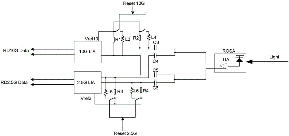
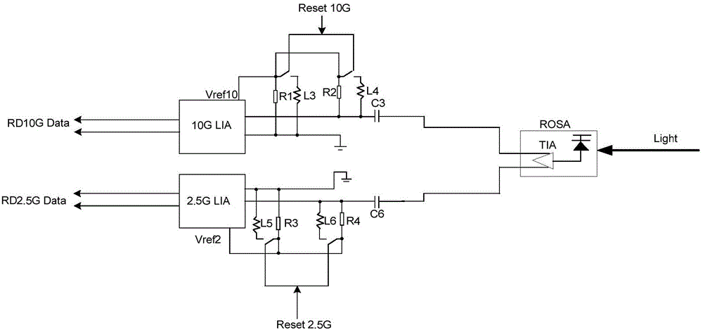
The embodiment of the invention discloses an optical module and an optical signal receiving circuit. The optical signal receiving circuit comprises a receiver optical subassembly which is used for receiving burst uplink optical signals and converting the uplink optical signals into electric signals, wherein the uplink optical signals comprise a high-rate optical signal and a low-rate optical signal; a rate select switch of which electric signal input end is connected with the electric signal output end of the receiver optical subassembly, wherein the rate select switch is used for selecting a control signal according to a rate of a control unit and outputting the electric signals output by the rate select switch to a high-rate signal limit-amplitude amplifier or a low-rate signal limit-amplitude amplifier; the high-rate signal limit-amplitude amplifier of which input end is connected with the output end of the rate select switch; and the low-rate signal limit-amplitude amplifier of which input end is connected with the output end of the rate select switch. According to the technical scheme provided by the optical module and the circuit, the uplink receiving sensitivity for the XG-PON1 and XGS-PON double-rate optical signals is improved to a great extent.

Description

technical field [0001] The invention relates to the technical field of optical communication, in particular to an optical module and an optical signal receiving circuit. Background technique [0002] With the rapid development of technologies such as cloud computing, high-definition video, and virtual reality, user bandwidth is also increasing rapidly. According to Nielsen's law, bandwidth demand will increase by an order of magnitude every seven years. Existing access network technologies need to be continuously upgraded to adapt to growth. bandwidth and technical requirements. The PON (Passive Optical Network, Passive Optical Network) network based on the point-to-multipoint topology is currently the mainstream broadband access technology, and the higher-speed PON technology is gradually becoming a research hotspot in the industry. Up to now, a series of industry standards for PON technology have been released, specifying detailed technical parameters and indicators, main...

Claims


Application Information

Patent Timeline
IPC IPC(8): H04B10/60H04Q11/00
CPCH04B10/60H04Q11/0067
Inventor 张强杨世海王雪阳
Owner HISENSE BROADBAND MULTIMEDIA TECH
Why Eureka
Try Eureka