Airborne wingtip smoke puller
A smoke puller and wingtip technology, which is applied in the field of airborne wingtip smoke pullers, can solve the problems of easy recovery into a fighter jet state, and achieve the effects of light weight, small cross-sectional area, and small volume
Active Publication Date: 2012-09-12
CHENGDU AIRCRAFT INDUSTRY GROUP
View PDF0 Cites 3 Cited by
- Summary
- Abstract
- Description
- Claims
- Application Information
AI Technical Summary
Problems solved by technology
Easy to revert to fighter status
Method used
View moreImage
Smart ImageViewing Examples
Examples
Embodiment Construction
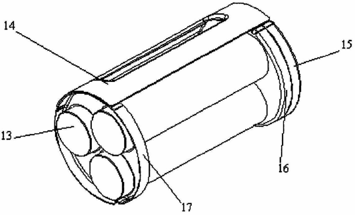
[0018] The reinforcing plate 14 is installed on the cylindrical surface of the chimney 9. The beam and the arc surface of the chimney are connected with screws. Pull at the connection
Login to View More PUM
 Abstract
The invention relates to an airborne wingtip smoke puller used for flight performances. The front end of the chimney made of light material is connected with a conical fluid fairing. Inside the chimney, there are three triple-ignition smoke bomb ballasts arranged in the shape of "pin" or "one" in parallel. In the hollow structure of the chimney The peripheral surface is fixedly connected with bolts to connect the suspension beam of the wing tip and two front shoulder shafts 5 and rear shoulder shafts 7 that are fixedly connected on the suspension beams. The frustum of a circle with the surface in contact with the airfoil. The invention adopts the "product" character array cabin light-weight smoke tube and the conical fluid fairing connected to it, which is composed of three times of ignition and smoke in parallel. It has a good aerodynamic shape, the smallest outline size, small cross-sectional area, small volume and weight. Light advantage. It can meet the comprehensive factors of overall aerodynamics and strength limit. The contact between the top surface of the beam body and the airfoil is avoided by the two round tables assembled on the front and rear shoulder shafts on the upper part of the beam body. It provides an easy way for the show machine to restore to a fighter.
Description
Technical field of airborne wingtip smoke puller [0001] The present invention is used for the airborne wingtip smoke device of flight performance. Background technique In the prior art, the smoke release device that is usually installed on wingtip, belly or tail usually adopts fuming effective Time-limited fume cans, nozzles or small pods for smoke pulling devices during air performances. Its smoking forms include liquid smoking and Solid smoke. Liquid smoke requires the use of various smoke agents, and is connected to the smoke opening and closing control system through the original cable on the aircraft. system and color switching control system. The smoke-drawing agent is sprayed from the nozzle of the smoke-drawing nozzle, and under the action of the tail flow of the tail nozzle, it is required Atomization molding in a very short time. The solid smoke puller requires the control of the on-board launch system, which needs to be restored after quitting the perfor...
Claims
Login to View More Application Information
Patent Timeline
 Patent Type & Authority Patents(China)
IPC IPC(8): B64D1/16
Inventor 向加全
Owner CHENGDU AIRCRAFT INDUSTRY GROUP
Features
- R&D
- Intellectual Property
- Life Sciences
- Materials
- Tech Scout
- Unparalleled Data Quality
- Higher Quality Content
- 60% Fewer Hallucinations
Learn More Browse by: Latest US Patents, China's latest patents, Technical Efficacy Thesaurus, Application Domain, Technology Topic, Popular Technical Reports.
© 2025 PatSnap. All rights reserved.Legal|Privacy policy|Modern Slavery Act Transparency Statement|Sitemap|About US| Contact US: help@patsnap.com


