
Large transparent flotation column for dynamics research of mineral machining

A technology of dynamics and flotation columns, which is applied in the field of large transparent flotation columns for mineral processing dynamics research, can solve the problems of insufficient tolerance, high cost, and no equipment invention and use, etc., to improve the convenience of use Good resistance, good compressive strength and good light transmission

Active Publication Date: 2017-03-22
YUNNAN PHOSPHATE CHEM GROUP CORP
View PDF7 Cites 4 Cited by
  • Summary
  • Abstract
  • Description
  • Claims
  • Application Information

AI Technical Summary

Problems solved by technology

Therefore, it is of great significance to carry out research on the dynamics of flotation columns. How to observe and record the movement laws of gas, solid and liquid in the flotation column is a difficult problem in the industry, because the cost of using glass to make large containers is high and the tolerance is high. There is no need, and no related equipment has been invented and used

Method used


Image

  • Large transparent flotation column for dynamics research of mineral machining
  • Large transparent flotation column for dynamics research of mineral machining
  • Large transparent flotation column for dynamics research of mineral machining

Examples


Embodiment 1

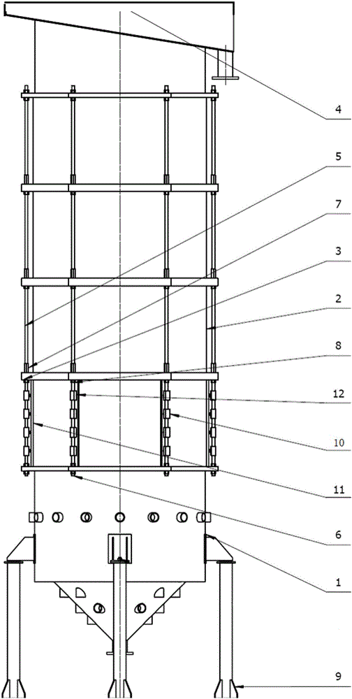
[0028] Embodiment 1: as figure 1 As shown, a large-scale transparent flotation column for mineral processing dynamics research includes several support columns 9, a lower column 1 installed on the support column 9, a bottom cone is installed on the bottom surface of the lower column 1, and the bottom cone There are several foamer interfaces on the body, and a number of supporting devices extending upwards are installed on the upper part of the lower column body 1. The top of the supporting device is connected to the upper column body 4, and the supporting device is tightly attached to the lower column body 1 and the upper column body. Body 4 is connected to the outside of transparent cylinder 2. The support column 9 is placed on the foundation, the lower column 1 is fixed in the middle of the support column 9, a foamer is installed on the bottom cone, the transparent column 2 is placed above the lower column 1, and its top is connected to the upper column 4, When in use, the ...

Embodiment 2

[0031] Embodiment 2: as figure 2 , image 3 As shown, on the basis of Example 1, the transparent glass cylinder is composed of several sections of annular glass longitudinally, the lower end of the lowermost annular glass is connected and installed on the lower column 1, and the uppermost annular glass The upper end of the ring glass is connected and installed on the upper column 4, the upper end of the lowermost annular glass, the lower end of the uppermost annular glass and the upper and lower ends of each remaining section of annular glass are butt-connected and installed on the connecting ring 3 rings . The upper and lower sides of the connecting ring 3 rings are provided with placement grooves corresponding to the thickness of the annular glass, which are used to place and fix the annular glass. Due to the large size of the flotation column, it is too difficult to design a whole transparent glass body And the bearing capacity is reduced. Therefore, the use of multi-seg...

Embodiment 3

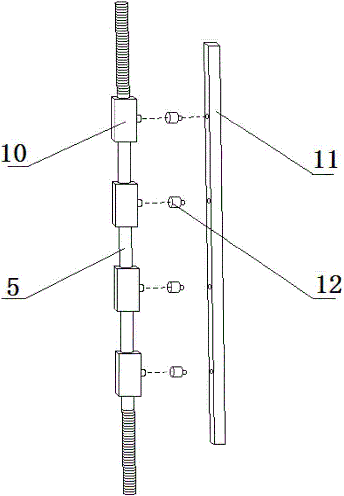
[0034] Embodiment 3: as Figure 4 As shown, on the basis of Embodiment 1, the structure of the supporting device is changed, and only a few connecting screws 5 are tightly fixed to the outer wall of the transparent cylinder 2 for support. The ring glass is made of laminated glass. The ring glass is made of laminated glass. Good compressive strength, good light transmission, easy to observe the operation of gas, solid and liquid three phases inside the equipment.


PUM


Abstract

The invention relates to mechanical equipment of dynamics research in the process of mineral machining, in particular to a large transparent flotation column for dynamics research of mineral machining. The large transparent flotation column comprises supporting bases and a base column barrel body. A bottom conical body is arranged on the bottom face of the base column barrel body, and foam maker connecting ports are formed in the bottom conical body. A plurality of supporting bars are arranged above the base column barrel body and extend upwards to be connected to an upper column body at the top end of the flotation column, and the supporting bars are evenly arranged and attached to the outer side of a transparent column body communicating with the base column barrel body and the upper column body. According to the large transparent flotation column for dynamics research of mineral machining, compressive strength and light transmission are good, and running circumstances of gas, solid and liquid phases in equipment are conveniently observed; double guarantee for the light transmission degree and the firmness degree of a large flotation test flotation column can be taken into consideration; and equipment height is conveniently adjusted, foam makers can be transversely and vertically installed, and the foam makers of different quantities and specifications can be installed according to the requirement, so that conducting of dynamics research of mineral machining is facilitated.

Description

technical field [0001] The invention relates to a mechanical device for the dynamics research of the mineral processing process, in particular to the research of the operating parameters of the equipment in the flotation process, specifically a large transparent flotation column for the dynamics research of the mineral processing. Background technique [0002] With the rapid development of the phosphate fertilizer industry, the mining and consumption of phosphate rock have also increased sharply, and the overall grade of phosphate rock has been declining, resulting in more and more complex impurity components in phosphate rock. The development of medium and low-grade phosphate rock has become a top priority. For medium and low-grade calcareous collophosite, the main impurity is carbonate impurities. At present, a single reverse flotation process is mainly used to remove carbonate impurities and enrich useful ores. It is relatively simple in the collophosite sorting. The flo...

Claims


Application Information

Patent Timeline
Patent Type & Authority Applications(China)
IPC IPC(8): B03D1/14B03D1/02B03D103/06
CPCB03D1/021B03D1/14B03D2203/06
Inventor 李耀基宋慧林刘丽芬张朝旺李若兰彭千山戴川王灿霞字佳林
Owner YUNNAN PHOSPHATE CHEM GROUP CORP
Learn More