
Cutter for cutting machine tool

A technology for cutting machine tools and tools, which is applied in the field of tool tools for machine tools to achieve the effect of ensuring the cutting effect and simplifying the structure

Inactive Publication Date: 2017-03-22
CHONGQING HUANDAO MACHINERY MFG CO LTD
View PDF0 Cites 0 Cited by
  • Summary
  • Abstract
  • Description
  • Claims
  • Application Information

AI Technical Summary

Problems solved by technology

[0003] The present invention intends to provide a cutter for cutting machine tools to solve the problem that pressurization equipment is required to pressurize the water in advance when the cutter is working

Method used


Image

  • Cutter for cutting machine tool

Examples


Embodiment Construction

[0016] The present invention will be described in further detail below by means of specific embodiments:

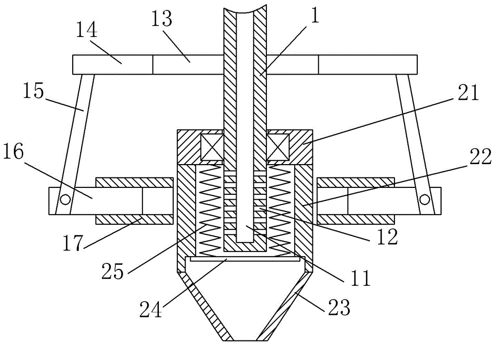
[0017] The reference signs in the drawings of the description include: rotating shaft 1, water inlet hole 11, drain port 12, driving gear 13, driven gear 14, connecting rod 15, pressing rod 16, chute 17, nozzle seat 21, elastic member 22 , Nozzle 23, pressing plate 24, extension spring 25.

[0018] The embodiment is basically as attached figure 1 Shown: a cutter for cutting machine tools, including a nozzle, the nozzle includes a nozzle seat 21, an elastic member 22 and a nozzle 23 from top to bottom, a working chamber is formed between the nozzle seat 21, nozzles 23 and the elastic member 22, and the elastic A first groove is also provided on the part 22, and a pressing plate 24 is arranged in the first groove, and the axial width of the pressing plate 24 is smaller than the axial width of the first groove, and the pressing plate 24 divides the working chamber into the ...


PUM


Abstract

The invention discloses a cutter for a cutting machine tool. The cutter comprises a rotary shaft and a spray head. The spray head comprises a spray head base and a nozzle. The spray head base and the nozzle are connected through an elastic part. A first groove is formed in the elastic part. A pressing plate is arranged in the first groove. The cutter further comprises a tension spring. A working cavity is formed among the spray head base, the nozzle and the elastic part. The pressing plate divides the working cavity into a first working cavity and a second working cavity. The rotary shaft stretches into the first working cavity and is provided with a driving gear. The two ends of the driving gear are engaged with driven gears correspondingly. The driven gears are provided with connection rods, and pressing rods are hinged to the connection rods. The rotary shaft is further provided with a water inlet hole, the portion, stretching into the first working cavity, of the rotary shaft is provided with a plurality of water outlets, and the water outlets are made communicated with the water inlet hole. According to the scheme, when the cutter is used for machining a workpiece, no additional pressurization equipment is needed for pressurizing water, and therefore the structure of the whole cutting machine tool is simplified.

Description

technical field [0001] The invention relates to a tool for a machine tool. Background technique [0002] The cutting machine tool is mainly used for cutting and processing the workpiece. The cutting tool on the cutting machine tool is one of the important parts on the cutting machine tool. The existing tool is mainly a water jet. Water is sprayed from a small nozzle to form a high-speed jet, and the power of this high-speed jet is used to cut the workpiece. When cutting the workpiece, this kind of tool needs to add additional pressurized equipment. The pressurized equipment needs to pressurize the water in advance. pressure, and then pass the pressured water into the cutter. At the same time, the cutter often has different water pressure requirements when cutting different workpieces. At this time, different pressurization equipment needs to be connected, so that the entire cutting machine tool The structure becomes very complicated. Contents of the invention [0003] Th...

Claims


Application Information

Patent Timeline
Patent Type & Authority Applications(China)
IPC IPC(8): B23D79/00
CPCB23D79/00
Inventor 苏纽
Owner CHONGQING HUANDAO MACHINERY MFG CO LTD
Learn More