
Water-cooling wall pipe replacing process

A water-cooled wall and process technology, applied in the field of pipe changing process, can solve the problems of high working intensity, poor working environment, high risk, etc., and achieve the effect of saving time

Inactive Publication Date: 2017-03-22
SHANGHAI SHANGDIAN CAOJING POWER GENERATION
View PDF7 Cites 4 Cited by
  • Summary
  • Abstract
  • Description
  • Claims
  • Application Information

AI Technical Summary

Problems solved by technology

Thirdly, it takes a lot of time to erect and dismantle the scaffolding, especially for the tower furnace, from the furnace bottom elevation of 4 meters to the elevation of the middle header of the water-cooled wall of 70 meters. It’s okay, but it’s dangerous to ride it up, and it takes time and is very dangerous to use a hanging cage
[0004] This kind of water-cooled wall is routinely changed, and people have to enter the furnace. The working environment is poor, the work intensity is high, and they have to climb tens of meters of scaffolding. The scaffolding is full of dust, which is very dangerous.

Method used


Image

  • Water-cooling wall pipe replacing process
  • Water-cooling wall pipe replacing process

Examples


Embodiment 1

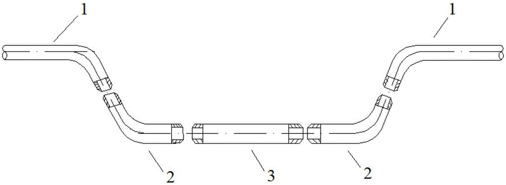
[0029] A water-cooled wall pipe replacement process, the schematic diagram of the decomposition structure of the welded pipe is as follows figure 1 As shown, the tube replacement process uses the following steps:

[0030] (1) The boiler is shut down, and the furnace is stuffy until the manhole door can be opened, check the leaking pipes in the water cooling wall, and cut out the gap at the corresponding position of the water cooling wall;

[0031] (2) To cut the leaking part of the pipeline, it is necessary to detect the metallographic structure of the pipe part, and the cutting length is until the metallographic structure of the pipe part is intact;

[0032] (3) Cut off the fins at both ends of the remaining unleaked old elbow 1, use the hot bending method to bend the two ends of the pipe and pull it out from the gap of the gas cutting on the boiler. The fins at both ends of the leaked pipe are baked with a drying gun, and pulled out of the furnace with a chain hoist. After ...

Embodiment 2

[0035] A water-cooled wall pipe replacement process adopts the following steps:

[0036] After the boiler is shut down, the furnace is so stuffy that the manhole door can be opened, and a person uses a strong flashlight outside the manhole door to check the water wall. If there is a trace of water at the leak, the location of the leak can be determined. Since the furnace has been stuffy for more than 30 hours at this time, the boiler pressure is not very high. Use gas to cut a small slit on the sheet, and at the same time use a strong flashlight at the manhole door to observe the leak point in the furnace and the position of the gas cutting Mars, guide the gas cutter to cut a small slit on the fin and approach the leak point, and finally find the exact leak point and leak pipe. Since the small slit of the fins at the leak point is cut, water can be seen spraying out of the leak point outside the furnace, so it will be easy and intuitive to determine the leak point and the leak...


PUM


Abstract

The invention relates to a water-cooling wall pipe replacing process. The process includes the following steps that (1) a boiler is shut down and subjected to blocking till a manhole door can be opened, a leaking pipe in a water-cooling wall is checked, and a gap is formed in corresponding position of the water-cooling wall through gas cutting; (2) a leaking pipe section of the pipe is cut off; (3) fins at the two ends of the remaining non-leaking pipe are cut apart, a hot bending method is used for bending the two ends of the pipe, and the pipe is pulled out from the gas-cut gap in the boiler; and (4) standby pipes are connected with the two ends of the pulled-out pipe, and the pipe replacing process is completed. Compared with the prior art, pipe replacing rush-repairing work can be completed outside the boiler, an operator does not need to enter a hearth, and thus safety is improved and cost is lowered.

Description

technical field [0001] The invention relates to a tube changing process, in particular to a water-cooled wall tube changing process. Background technique [0002] In recent years, in order to save energy and reduce emissions, a large number of 1000MW generating units have been constructed, and T23 new steel has been applied to the water wall. This T23 material was put into production and with the extension of the operation period of the unit, there were common occurrences of weld crack leakage and pipe burst accidents on the water-cooled wall construction site, resulting in many unplanned downtime accidents, which seriously affected the safety of several million-level generating units. Production, economic loss is huge. [0003] For emergency repair of water-cooled wall leaks, various power plants often use shutdown, stuffy furnace, natural cooling, fan ventilation, leak detection, scaffolding or use of hanging cages, cutting off leaking pipes, welding and replacing pipes, ...

Claims


Application Information

Patent Timeline
Patent Type & Authority Applications(China)
IPC IPC(8): B23P11/00
CPCB23P11/00
Inventor 屠志球
Owner SHANGHAI SHANGDIAN CAOJING POWER GENERATION
Learn More