Cotton cloth attachment anti-adhesion yarn winding device

A winding device and yarn technology, used in transportation and packaging, thin material handling, and filamentary material transportation, can solve the problems of rough winding, affecting production processes, equipment pollution, etc., to increase the working area, improve Anti-sticking effect, effect of improving stability

Inactive Publication Date: 2017-03-22
苏州市朗润纺织科技有限公司
View PDF13 Cites 5 Cited by
  • Summary
  • Abstract
  • Description
  • Claims
  • Application Information

AI Technical Summary

Problems solved by technology

In the spinning production process, due to seasonal climate, workshop temperature and humidity, raw materials and equipment, etc., the cotton laps produced in the workshop often have sticking during the winding process. After sticking, it will directly affect the carding process. The weight of sliver and carding effect will ultimately affect the consistency of yarn quality in subsequent processes
At present, in order to prevent the cotton laps from sticking, most enterprises will place rough yarns between the cotton lap layers, but the current winding device has defects, and there are windings during the winding process of the cotton laps and anti-stick yarns. Roughness, winding jamming and other phenomena affect the production process, and in the process of cotton cloth transmission, cotton cloth produces a large amount of cotton wool, dust and other debris, which pollutes the equipment and affects the progress of the production process

Method used


Image

  • Cotton cloth attachment anti-adhesion yarn winding device
  • Cotton cloth attachment anti-adhesion yarn winding device

Examples


Embodiment Construction

[0014] In order to make the technical means, creative features, goals and effects achieved by the present invention easy to understand, the present invention will be further described below in conjunction with specific embodiments.

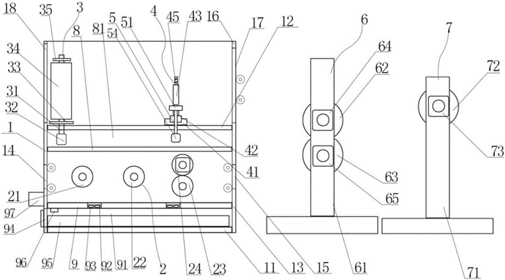
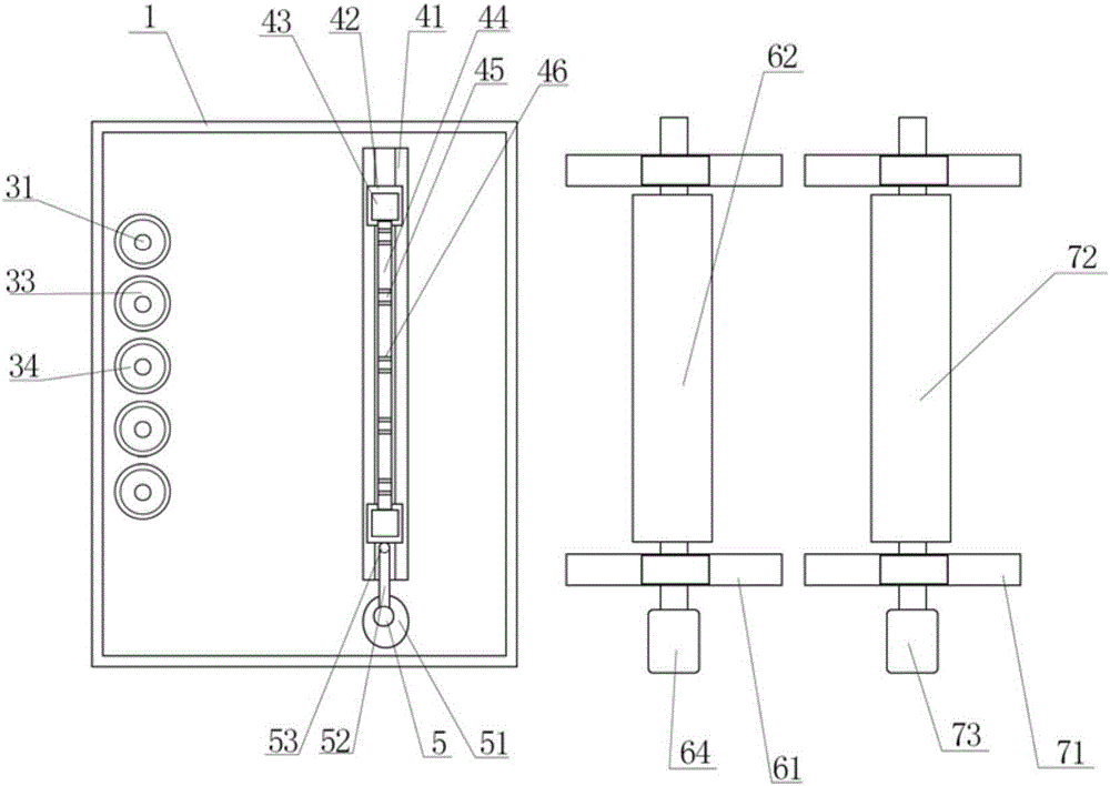
[0015] Such as figure 1 and figure 2 As shown, a cotton cloth bonding anti-adhesive yarn winding device of the present invention includes a frame 1, a base plate 11 is provided at the bottom of the frame 1, a horizontal plate 12 is provided at the middle of the frame 1, and a horizontal plate 12 is provided below the horizontal plate 12. A partition 8 is arranged horizontally, and an accommodating cavity 81 is formed between the partition 8 and the horizontal plate 12. The side of the frame 1 includes a lower side plate 13 arranged between the bottom plate 11 and the horizontal plate 12 and a The upper side plate of the upper part, the upper part of the bottom plate 11 is provided with a lap conveying assembly 2, the horizontal plate 12 is provi...


PUM


Abstract

The invention discloses a cotton cloth attachment anti-adhesion yarn winding device. The cotton cloth attachment anti-adhesion yarn winding device comprises a rack. The bottom of the rack is provided with a bottom plate. The middle of the rack is provided with a transverse plate. A partition plate is horizontally arranged below the transverse plate. An accommodating cavity is formed between the partition plate and the transverse plate. A cotton roll conveying assembly is arranged above the bottom plate. A yarn unwinding assembly is arranged on the transverse plate. One side of the yarn unwinding assembly is provided with a swing mechanism. One side of the rack is provided with a pressing mechanism and a winding mechanism. A cleaning plate is horizontally arranged above the bottom plate. A cleaning cavity is formed between the cleaning plate and the bottom plate. The cleaning plate is uniformly provided with four cleaning holes which communicate with the cleaning cavity. Each cleaning hole is internally provided with a negative pressure draught fan. The side surface of the cleaning cavity is provided with a rectangular opening. A drawer is arranged in the cleaning cavity through the rectangular opening. One side of the bottom of the cleaning plate is provided with a water injection nozzle. The side surface of the rack is provided with a water tank which is connected with the water injection nozzle.

Description

technical field [0001] The invention relates to the technical field of textiles, in particular to a cotton cloth laminating and anti-adhesive yarn winding device. Background technique [0002] The original meaning of textile is taken from the general term of spinning and weaving, but with the continuous development and improvement of the textile knowledge system and subject system, especially after the emergence of non-woven textile materials and three-dimensional composite weaving technologies, the current textile is not only a traditional Hand spinning and weaving also include garment, industrial and decorative textiles produced by non-woven technology, modern three-dimensional weaving technology, and modern electrostatic nano-netting technology. In the spinning production process, due to seasonal climate, workshop temperature and humidity, raw materials and equipment, etc., the cotton laps produced in the workshop often have sticking during the winding process. After stic...

Claims


Application Information

Patent Timeline
Patent Type & Authority Applications(China)
IPC IPC(8): B65H54/28B65H51/08B65H54/70
CPCB65H51/08B65H54/28B65H54/702B65H2701/31
Inventor 朱峰
Owner 苏州市朗润纺织科技有限公司
Why Eureka
Try Eureka