
Method for reinforcing soil slope and slope reinforcing device

A soil slope and reinforcement device technology, applied in fertilization devices, chemical instruments and methods, excavation, etc., can solve the problems of large amount of slope reinforcement and high construction difficulty, and achieve self-stability enhancement, simple construction technology and equipment , Improve the effect of anti-slip force

Inactive Publication Date: 2017-03-22
重庆市基础工程有限公司
View PDF6 Cites 6 Cited by
  • Summary
  • Abstract
  • Description
  • Claims
  • Application Information

AI Technical Summary

Problems solved by technology

[0005] The first purpose of the present invention is to provide a method for reinforcing soil slopes to solve the technical problems of large amount of slope reinforcement and high construction difficulty in the prior art
[0006] The second purpose of the present invention is to provide a slope reinforcement device to solve the technical problems of large amount of slope reinforcement and high construction difficulty in the prior art

Method used


Image

  • Method for reinforcing soil slope and slope reinforcing device
  • Method for reinforcing soil slope and slope reinforcing device
  • Method for reinforcing soil slope and slope reinforcing device

Examples


Embodiment 1

[0048]The specific implementation of this embodiment is as follows:

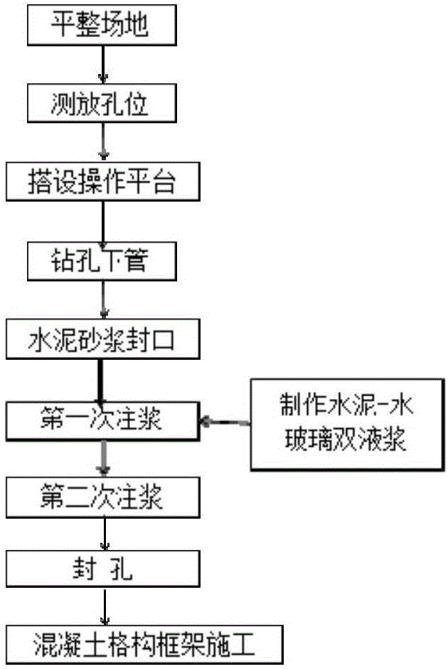
[0049] like Figure 1-5 As shown, a method for reinforcing soil slopes provided in this embodiment includes inserting steel flower tubes 8 and lattice beams into the slope, injecting grout into the steel flower tubes 8, and pouring concrete to the lattice beams. The specific steps are as follows:

[0050] Step 1: Level the site, remove obstacles, and take corresponding protection measures for the sites that need to be protected.

[0051] Step 2: measure the hole position, design the spacing according to the requirements, use the combination of instruments and manual measurement of the hole position, first use the total station to set the flower tube grouting axis, and then use the manual ruler to measure the position.

[0052] Step 3: Set up the operation platform and do a good job of safety protection.

[0053] Step 4: Drilling and lowering the tube, using the impact rotary extrusion and tube method to dr...

Embodiment 2

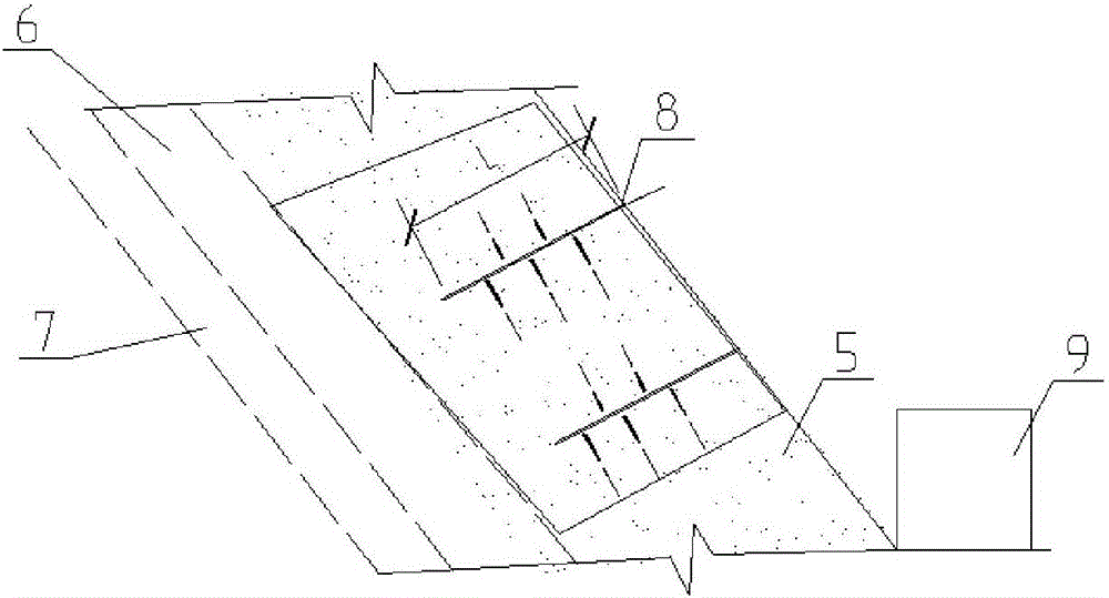
[0156] like Figure 2-4 As shown, a slope reinforcement device provided in this embodiment includes a steel floral tube 8 inserted on the slope and a concrete lattice beam 9 located below the steel floral tube 8. The steel floral tube 8 is arranged on the slope of the slope, and the concrete lattice The girder 9 is arranged at the bottom of the slope to prevent the slope from loosening and slipping.

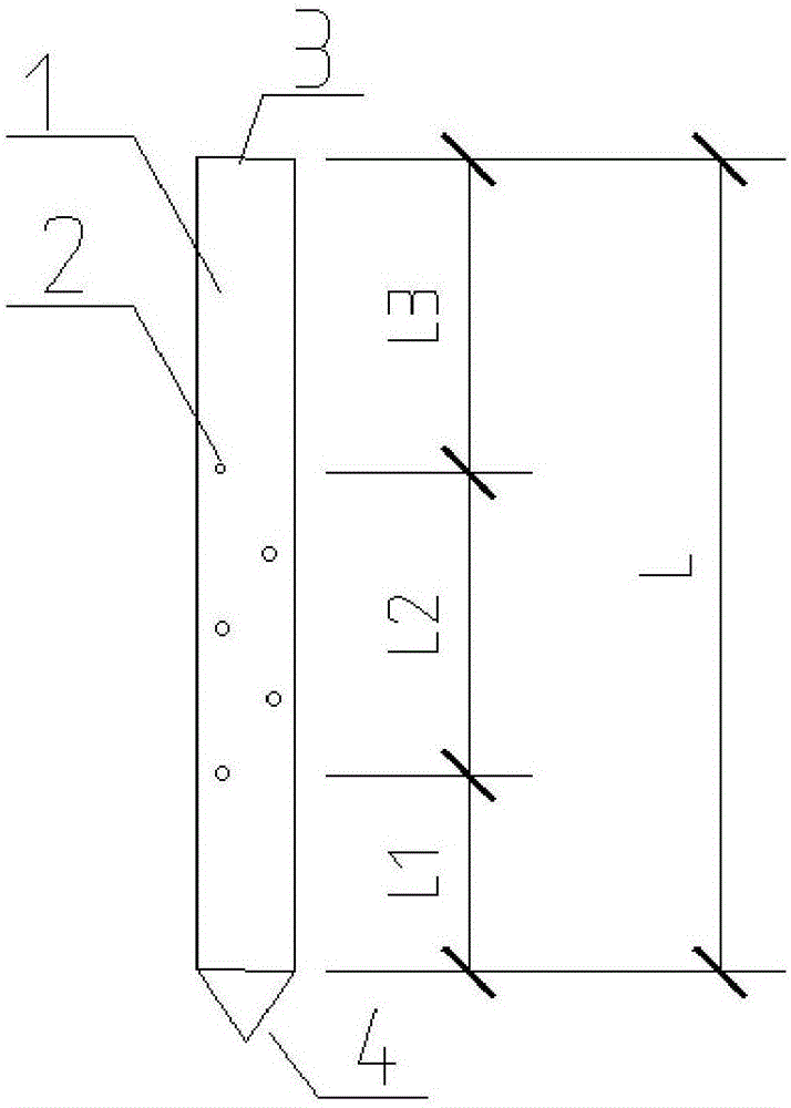
[0157] The head 4 of the steel flower tube is a pointed cone structure, and the wall 1 of the steel flower tube is provided with a plurality of slurry outlet holes 2 .

[0158] The concrete lattice beam 9 is a lattice beam frame covered and wrapped by a concrete layer.

[0159] Preferably, the pipe diameter of the steel flower pipe 8 is 50 mm in diameter.

[0160] Preferably, the axial spacing of each grouting hole 3 is 500 mm.

[0161] Specifically, the grouting hole 3 is set at a height below two-thirds of the steel flower tube 8 .

[0162] Specifically, the height of the c...


PUM


Abstract

The invention provides a method for reinforcing a soil slope and a slope reinforcing device and relates to the technical field of slope reinforcement. The technical problems that in the prior art, the slope reinforcing work amount is great and the construction difficulty is high are solved. The method for reinforcing soil slope comprises the steps of: inserting a steel flower tube and a lattice beam into the slope; grouting the steel flower tube; and pouring concrete into the lattice beam. The method specifically comprises: leveling a land; measuring and placing a hole site; erecting an operating platform; drilling a hole and descending a tube; performing sealing by cement mortar; and constructing the concrete lattice frame. The slope reinforcing device comprises the steel flower tube which is inserted into the slope and the concrete lattice beam which is located below the steel flower tube. The steel flower tube is arranged on the inclined slope, and the concrete lattice beam is arranged at the bottom of the slope; the head of the steel flower tube is of a cone-shaped structure, and a plurality of mortar outlet holes are formed in the wall of the steel flower tube; and the concrete lattice beam is the lattice beam frame which is covered and coated by a concrete layer. The method and device for reinforcing the soil slope provided by the invention are wide in range of application and simple in construction process.

Description

technical field [0001] The invention relates to the technical field of slope reinforcement, in particular to a soil slope reinforcement method and a slope reinforcement device. Background technique [0002] Accidents of deformation and failure of high slopes occur frequently, such as: water conservancy and hydropower, mines, highways, railways and military projects, etc., will encounter artificial excavation and naturally formed high and steep slopes. When the geological conditions are poor, rainwater is concentrated and If it is not handled properly, landslides may occur, and even serious landslide disasters may occur. Due to the rapid development of my country's economy at present, the scale of engineering construction is getting larger and larger, and the problem of landslides is becoming more and more prominent. Some experts estimate that the economic losses caused by geological disasters such as landslides in my country amount to 10 billion to 20 billion yuan every yea...

Claims


Application Information

Patent Timeline
IPC IPC(8): E02D17/20E02D15/02C09K17/12C09K103/00
CPCE02D17/20C09K17/12C09K2103/00E02D15/02E02D2250/003
Inventor 章澎卫延涛贺福洋王伟
Owner 重庆市基础工程有限公司
Learn More