Built-in truss combined structure

A combined structure and truss technology, applied to building components, building structures, walls, etc., can solve problems such as complex manufacturing process and wall thickness restrictions, and achieve good mechanical properties and superior energy consumption.

Inactive Publication Date: 2017-03-22
浙江中南绿建科技集团有限公司
View PDF8 Cites 1 Cited by
  • Summary
  • Abstract
  • Description
  • Claims
  • Application Information

AI Technical Summary

Problems solved by technology

However, the current steel pipe bundle structure is welded by steel plates, and the manufacturing process is complicated. If U-shaped steel is used for splicing, the wall thickness is limited by the process.

Method used


Image

  • Built-in truss combined structure
  • Built-in truss combined structure
  • Built-in truss combined structure

Examples


Embodiment 1

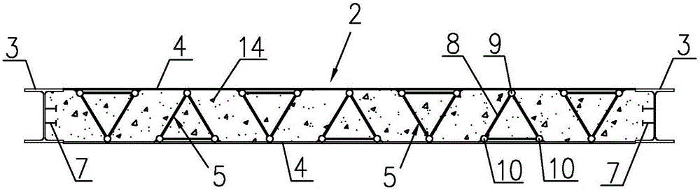
[0041] Embodiment 1 includes a combined body 2, the combined body 2 is composed of an end column 3 and a steel plate 4, and the end column 3 and the steel plate 4 are welded and fixed. The steel plates 4 on both sides are arranged in parallel up and down, and the end columns 3 are fixed on both ends of the steel plates 4, and the two end columns 3 and the two steel plates 4 form a straight shape. A cavity is formed between the end column 3 and the steel plate 4, and a triangular truss 5 is separately arranged in the cavity, and the triangular truss 5 is welded to the steel plate at equidistant distances, and two adjacent triangular trusses 5 are arranged in rotation. A shear member 7 is provided on the inner side of the end column, and two laterally adjacent shear members 7 are arranged symmetrically. Concrete 14 is poured in the cavity, and the triangular truss 5 and the shear member 7 are all set in the concrete 14 .

Embodiment 2

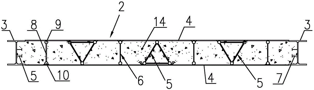
[0042] The second embodiment includes a combined body 2, the combined body 2 is composed of an end column 3 and a steel plate 4, and the end column 3 and the steel plate 4 are welded and fixed. The steel plates 4 on both sides are arranged in parallel up and down, and the end columns 3 are fixed on both ends of the steel plates 4, and the two end columns 3 and the two steel plates 4 form a straight shape. A cavity is formed between the end column 3 and the steel plate 4, and a triangular truss 5 and a planar truss 6 are arranged in cooperation with each other in the cavity. The distance is welded on the steel plate 4, and two adjacent triangular trusses 5 are arranged in rotation. A shear member 7 is provided on the inner side of the end column, and two laterally adjacent shear members 7 are arranged symmetrically. Concrete 14 is poured in the cavity, and the triangular truss 5 and the shear member 7 are all set in the concrete 14 .

[0043] Such as image 3 and Figure 4 ...

Embodiment 3

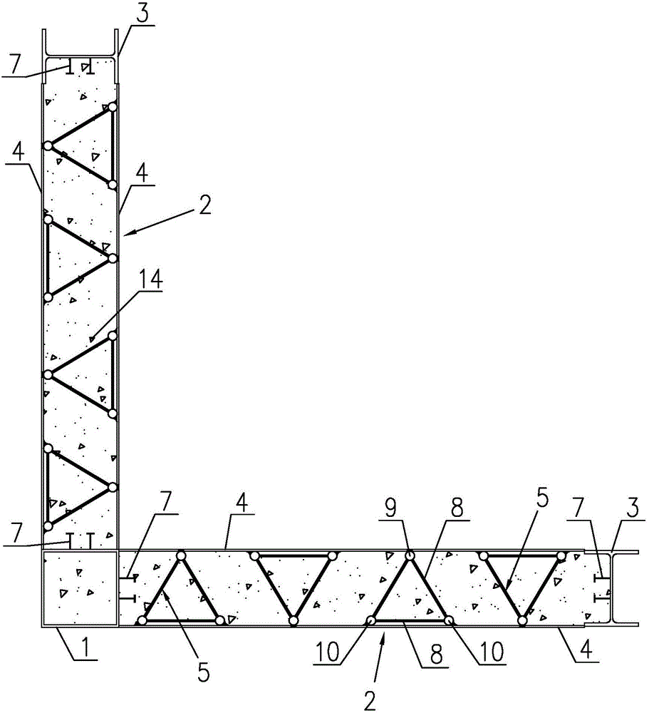
[0044]Embodiment 3 includes a combination body 2, one end of the combination body 2 is provided with a corner post 1, the corner post 1 adopts a rectangular tube or a square tube, the combination body 2 is arranged on two intersecting sides of the corner post 1, the corner post 1 and the two combination bodies 2 form an L shape. The combined body 2 includes an end column 3 and a steel plate 4, and the end column 3 and the steel plate 4 are fixed by welding. The steel plates 4 on both sides are arranged in parallel up and down, and the steel plates 4 are fixed between the end columns 3 and the sides of the corner columns 1 . A cavity is formed between the end column 3, the steel plate 4 and the corner column 1, and a triangular truss 5 is separately arranged in the cavity, and the triangular truss 5 is welded to the steel plate 4 at equal distances, and two adjacent triangular trusses 5 are rotated. The inner side of the end column 3 is provided with a shear member 7, and two ...


PUM


Abstract

The invention discloses a built-in truss combined structure which comprises a combined body. The combined body is composed of steel plates and end columns. A cavity is formed among the end columns and the steel plates. Trusses are arranged in the cavity and fixed to the steel plates in a welded mode. Each truss comprises web members and chord members, wherein the chord members are fixed to the corresponding steel plates in a welded mode. Shear resisting components are arranged on the inner sides of the end columns. Concrete is poured in the cavity. The trusses and the shear resisting components are all arranged in the concrete. According to the built-in truss combined structure, advantages of steel and the concrete are fully achieved, and the structure has an excellent energy-dissipating capacity and a good mechanical property; the trusses are fixed to the steel plates in the welded mode, the steel plates on the two sides are restrained through the trusses, and premature occurrence of local buckling of the steel plates in the construction and use stage is prevented; and meanwhile, the cavity formed by the end columns and the steel plates can serve as a template for concrete pouring, and the construction cost is lowered.

Description

technical field [0001] The invention relates to the technical field of multi-story building structures, in particular to a built-in truss composite structure. Background technique [0002] The usual structural systems of multi-story building structures include frame structure, frame-support structure, frame-shear wall structure, shear wall structure, frame-tube structure, and tube-in-tube structure. In the above structural systems, the frame structure has the lowest building height, in order The height increases progressively, and the tube-in-tube is the highest. [0003] Shear walls are widely used in high-rise buildings because of their superior mechanical properties. In high-rise buildings, they mainly bear horizontal loads and vertical loads (gravity) caused by wind loads or earthquakes. cut) to destroy. Shear walls are divided into plane shear walls and cylindrical shear walls: plane shear walls are used in reinforced concrete frame structures, raised slab structures,...

Claims


Application Information

Patent Timeline
Patent Type & Authority Applications(China)
IPC IPC(8): E04B2/58E04B1/19
CPCE04B2/58E04B1/19
Inventor 王宇伟李志安王再胜王俊杰王海山
Owner 浙江中南绿建科技集团有限公司
Why Eureka
Try Eureka