Assembled board-column structure floor slab, dividing method thereof, and floor slab unit components

A slab-column structure and prefabricated technology, applied in floors, building components, building structures, etc., can solve the problems of high technical requirements of construction personnel, few applications, resistance and other problems, and achieve direct and simple force transmission, direct and simple structure, The effect of reducing complexity

Active Publication Date: 2017-03-22
刘祥锦
View PDF5 Cites 8 Cited by
  • Summary
  • Abstract
  • Description
  • Claims
  • Application Information

AI Technical Summary

Problems solved by technology

In this form, the compressive stress of the friction force comes from the post-tensioned prestressed steel strands on site. Because of the special requirements of the connection, the construction process of the prestressed steel strands is cumbersome and difficult, which is very difficult for the construction personnel. The technical requirements are very high; in addition, the prestressing purpose of the node tension is for the connection, and additional stress is generated on the original assembled components, which not only increases the design difficulty but also affects the project cost; and when using the "IMS" system , prestressed friction joints not only need to meet the relevant regulations of reinforced concrete structures, but also meet the requirements of "Technical Regulations for Integral Prestressed Prefabricated Slab-Column Structures CECS52: 2010", which is only an association standard regulation, not a national standard. From On the other hand, it indirectly shows that there are some problems in the connection me

Method used


Image

  • Assembled board-column structure floor slab, dividing method thereof, and floor slab unit components
  • Assembled board-column structure floor slab, dividing method thereof, and floor slab unit components
  • Assembled board-column structure floor slab, dividing method thereof, and floor slab unit components

Examples


Example Embodiment

[0050] Example 1

[0051] The fabricated slab-column structure floor of this embodiment and its dividing method and floor unit components are implemented in the following manner:

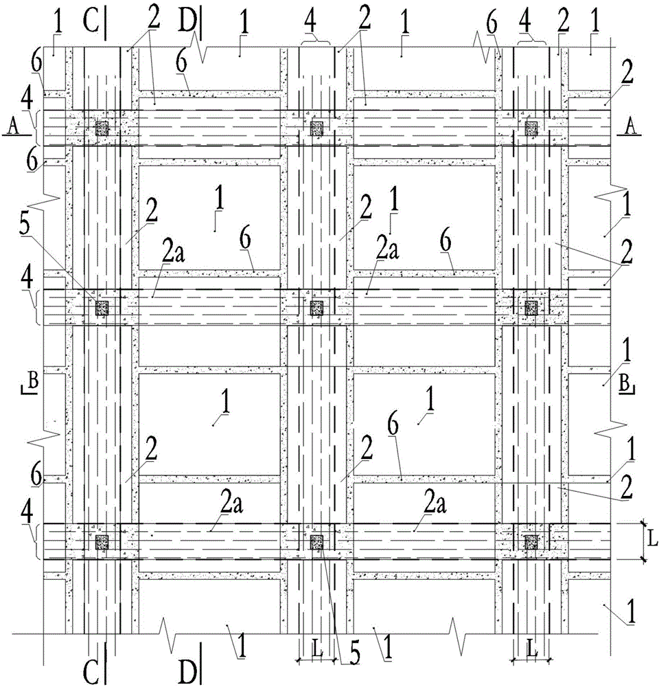
[0052] Such as figure 1 , Figure 5-6 , Figure 8 As shown in Figures 11-14, the fabricated slab-column structure floor slab includes (divided into) a number of prefabricated floor unit components including adjacent column connecting strips 4 and a number of conventional prefabricated floor unit components 1. These include Between the prefabricated floor unit members of the adjacent column connecting strips 4 and between the prefabricated floor unit members containing the adjacent column connecting strips 4 and the structural columns 5 are connected by a post-cast concrete connecting strip 6, the conventional prefabricated floor slab The unit components 1 and between the conventional prefabricated floor unit components 1 and the prefabricated floor unit components including adjacent column connecting str...

Example Embodiment

[0058] Example 2

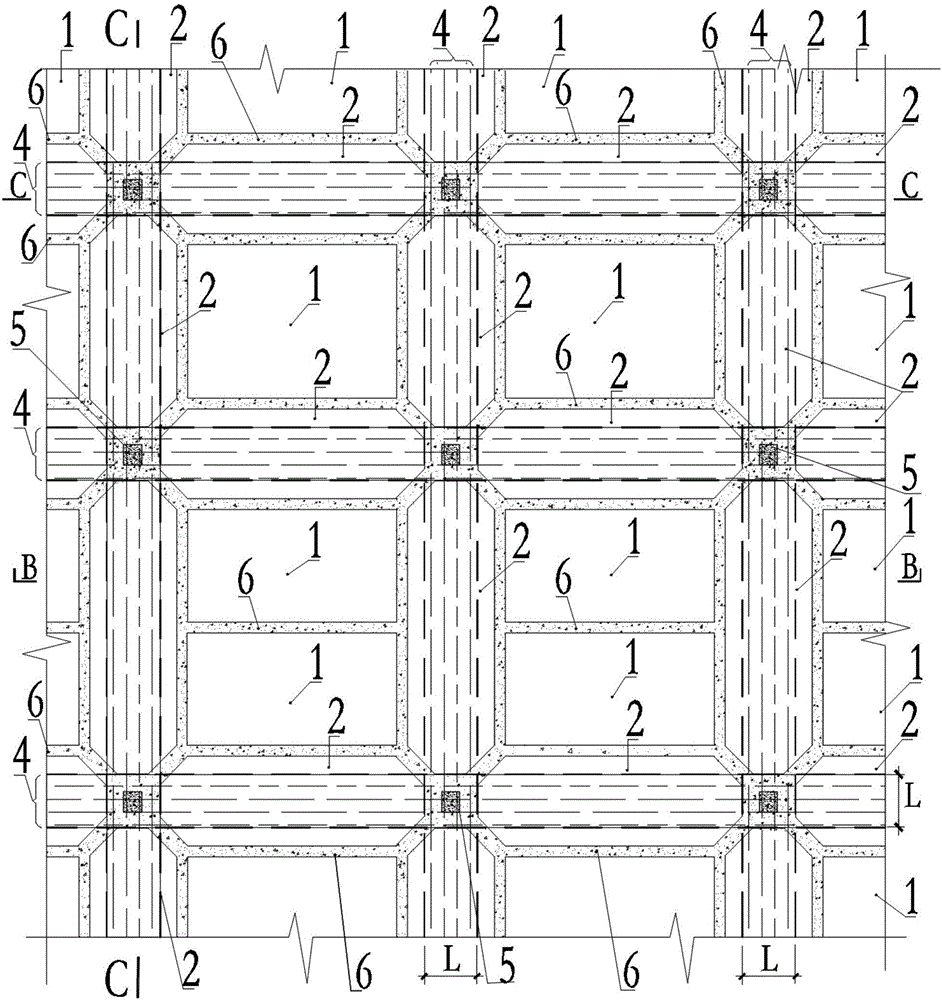
[0059] Such as figure 2 , Figure 5 , Figure 7 with Figure 12-14 As shown, the difference between this embodiment and Embodiment 1 is that in this embodiment, in the B1 type prefabricated floor unit component 2, the conventional floor connecting strips located on both sides of the adjacent column connecting strips 4 The end face is provided with a 45° cut angle. And there is no B2 type prefabricated floor unit component 2a in this embodiment.

[0060] Referring to Figure 13(b), in this embodiment, the reinforcement of the adjacent column connecting strip 4 adopts a full-length concealed beam; and the bottom reinforcement 7 is prestressed to become a prestressed prefabricated floor unit member.

[0061] In this embodiment, other embodiments than those described above are performed with reference to Example 1.

Example Embodiment

[0062] Example 3

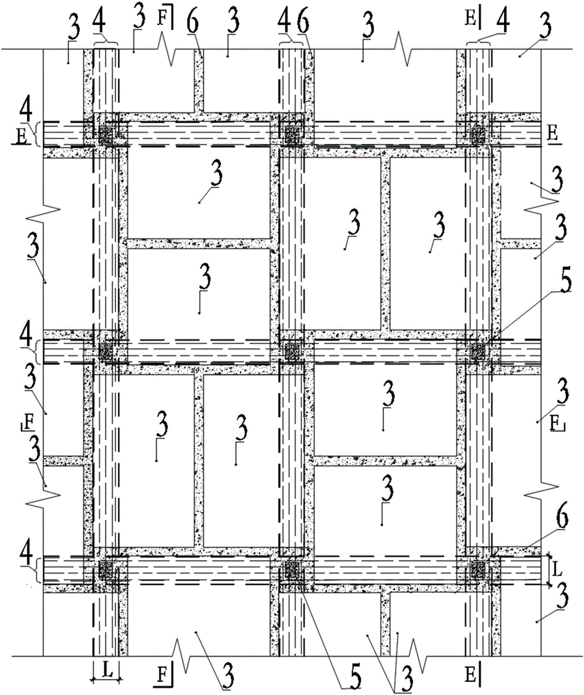
[0063] Such as image 3 , Figure 9-10 As shown in Figures 15-16, the difference between this embodiment and Embodiment 1 is that in this embodiment, the fabricated slab-column structure floor slab includes (divided into) several connecting plates containing adjacent columns Prefabricated floor unit members with 4, between these prefabricated floor unit members including adjacent column connecting strips 4, and between the prefabricated floor unit members including adjacent column connecting strips 4 and structural columns 5 after pouring The concrete connecting belt 6 is connected to form an integral floor. In this embodiment, the conventional prefabricated floor unit component 1 is not used.

[0064] See image 3 As shown in Figure 16, the prefabricated floor unit component including the adjacent column connecting strip 4 is the B3 type prefabricated floor unit component 3, which is centered on the adjacent column connecting strip 4 There is a conventional f...


PUM


Abstract

The invention discloses an assembled board-column structure floor slab, a dividing method thereof, and floor slab unit components. The assembled board-column structure floor slab comprises the multiple prefabricated floor slab unit components comprising adjacent column connection board belts, or the assembled board-column structure floor slab comprises the multiple prefabricated floor slab unit components comprising the adjacent column connection board belts, and the multiple conventional prefabricated floor slab unit components. The adjacent column connection board belts in the prefabricated floor slab unit components comprising the adjacent column connection board belts are long-strip-shaped belt boards integrally stretching across every two adjacent columns. The connection line of section centroids of the two adjacent structure columns connected through each adjacent column connection board belt serves as a reference line of the adjacent column connection board belt, and the width of each adjacent column connection board belt is larger than or equal to the longest side length of the connection sides of the two adjacent structure columns connected through the adjacent column connection board belt. The adjacent column connection board belts are provided with direct-through bottom reinforcing bars in the span direction. By the adoption of the technical scheme, cost can be reduced, construction is convenient, and safety and reliability of the board-column structure of the prefabricated floor slab can be improved at the same time.

Description

technical field [0001] The invention relates to a prefabricated assembled concrete structure and a method in the field of building industrialization, in particular to an assembled slab-column structure floor, a division method thereof, and a floor unit component. Background technique [0002] Since prefabricated buildings conform to the production method of environmental protection and energy saving, the country has proposed a development goal of making prefabricated buildings account for 30% of new buildings in about 10 years; It has the advantages of reducing the storey height, and has good economy in underground buildings and multi-storey parking garages. If the slab-column structure can be prefabricated, it will also have a large market space. [0003] Dismantling the building structure into components that can be produced in factories, transported, and installed easily, and that are safe, reliable, and economically reasonable is the key first step in the industrializati...

Claims


Application Information

Patent Timeline
IPC IPC(8): E04G21/00E04B5/02
CPCE04B5/02E04G21/00
Inventor 刘祥锦刘俊彦谭建山
Owner 刘祥锦
Why Eureka
Try Eureka