
Four-shaft machine tool calibration method based on multi-station measurement of laser tracker

A technology of laser tracker and calibration method, which is applied in the direction of measuring devices, instruments, and optical devices, and can solve the problems of being unable to meet the requirements of fast and efficient, multiple optical components, and long time consumption

Active Publication Date: 2017-03-22
BEIJING UNIV OF TECH
View PDF7 Cites 34 Cited by
  • Summary
  • Abstract
  • Description
  • Claims
  • Application Information

AI Technical Summary

Problems solved by technology

The commonly used machine tool error compensation method is to use high-precision optical instruments such as laser interferometers and autocollimators to directly separate the 21 errors of the machine tool, and then compensate each individual error separately. This method requires more optical components and needs to be aimed at It takes a long time to build corresponding optical paths for different error sources, which cannot meet the requirements of fast and efficient

Method used


Image

  • Four-shaft machine tool calibration method based on multi-station measurement of laser tracker
  • Four-shaft machine tool calibration method based on multi-station measurement of laser tracker
  • Four-shaft machine tool calibration method based on multi-station measurement of laser tracker

Examples


Embodiment Construction

[0095] The present invention will be further described in detail below in conjunction with the accompanying drawings, so that those skilled in the art can implement it with reference to the description.

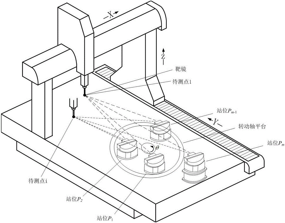
[0096] In the simulation experiment, the figure 1 The multi-station measurement system of the four-axis machine tool shown is used to measure the relative interference length measurement value, so the analysis is carried out through the following steps:

[0097] Step 1: Construct a multi-station measurement model of a four-axis machine tool laser tracker. Considering the measurement accuracy and the time required for the experiment, the number of laser tracker stations is determined to be 13, of which 12 stations are the stations where the laser tracker is fixed on the rotating shaft platform and the stations obtained after rotating 11 times. The 13th station is a station with a height difference from the 12th station. The number of space points to be measured in the four-a...


PUM


Abstract

The invention discloses a four-shaft machine tool calibration method based on the multi-station measurement of a laser tracker, and belongs to the technical field of precise testing. The method comprises the steps: firstly determining the coordinates of measurement points in a movement space range of a four-shaft machine tool, moving a target lens to each measurement point during measurement, enabling the laser tracker to carry out transfer measurement on a rotating shaft platform along with a rotating shaft, and obtaining the relative interference length measurement value of each measurement point to an initial measurement point at different station; secondly solving the coordinates of each station and the distance between the corresponding station to the initial measurement point through employing a formula for the distance between two points, the principle of least squares and a laser tracker station solving optimization algorithm; thirdly enabling the coordinates of the measurement points, the coordinates of the stations and the distances from the corresponding stations to the initial measurement point as the initial values, and solving and obtaining the correction value of each measurement point in the directions of three moving shafts of the four-shaft machine tool through the expansion of the first-order Taylor series of an interference length measurement error equation; finally building the mapping relation between the coordinate information of the stations of the laser tracker and the angle of the rotating shaft through circle fitting, and achieving the high-precision measurement of an rotating angle error of the rotating shaft.

Description

technical field [0001] The invention relates to a method for calibrating a four-axis machine tool, in particular a technical method based on multi-station laser tracking measurement, which belongs to the technical field of precision testing. Background technique [0002] Machine tools can realize high-precision and efficient processing and measurement of complex parts, which reflects the strength of a country's equipment manufacturing capabilities to a certain extent, and is an important indicator to measure the level of a country's manufacturing industry. Due to the late start of my country's machine tool research and relatively backward technical level, domestic machine tools still have a certain gap with developed countries such as Europe and the United States in the global market competition. The main reason is that domestic equipment is difficult to compete with developed countries in terms of stability, reliability and precision. Compared with advanced high-end equipmen...

Claims


Application Information

Patent Timeline
IPC IPC(8): G01B11/00
CPCG01B11/002
Inventor 陈洪芳郑博文石照耀孙衍强
Owner BEIJING UNIV OF TECH
Learn More