
High-power cylindrical gear comprehensive performance test bench with stepless adjustable center distance

A cylindrical gear and comprehensive performance technology, which is applied in the field of high-power cylindrical gear comprehensive performance test bench, can solve the problems of not being able to change the center distance at will, time-consuming and laborious disassembly, and staying in place, so as to meet long-term frequent tests and avoid repeated disassembly Fast assembly and disassembly

Inactive Publication Date: 2017-03-22
ZHEJIANG UNIV
View PDF8 Cites 18 Cited by
  • Summary
  • Abstract
  • Description
  • Claims
  • Application Information

AI Technical Summary

Problems solved by technology

[0004] At present, the international DCS-150 gear test bench, CL-100 gear test bench, JG-150 gear testing machine, ZHD82-A closed gear test bench, etc. cannot change the center distance at will, and disassembly and assembly are time-consuming and laborious. , the load cannot be changed during the test while loading
The common GTA-4, CLP-35S and other gear testing machines that can change the center distance are only suitable for gear testing with small power and small torque.
This makes it impossible for many gear manufacturers to objectively evaluate the quality of the gears they produce, and the inspection of gears is still at the level of using general-purpose low-precision equipment to roll the gear pair against each other to observe the meshing contact area of ​​the tooth surface.

Method used


Image

  • High-power cylindrical gear comprehensive performance test bench with stepless adjustable center distance
  • High-power cylindrical gear comprehensive performance test bench with stepless adjustable center distance
  • High-power cylindrical gear comprehensive performance test bench with stepless adjustable center distance

Examples


Embodiment Construction

[0031] Below in conjunction with accompanying drawing and example the present invention will be further described

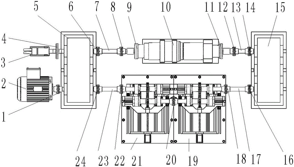
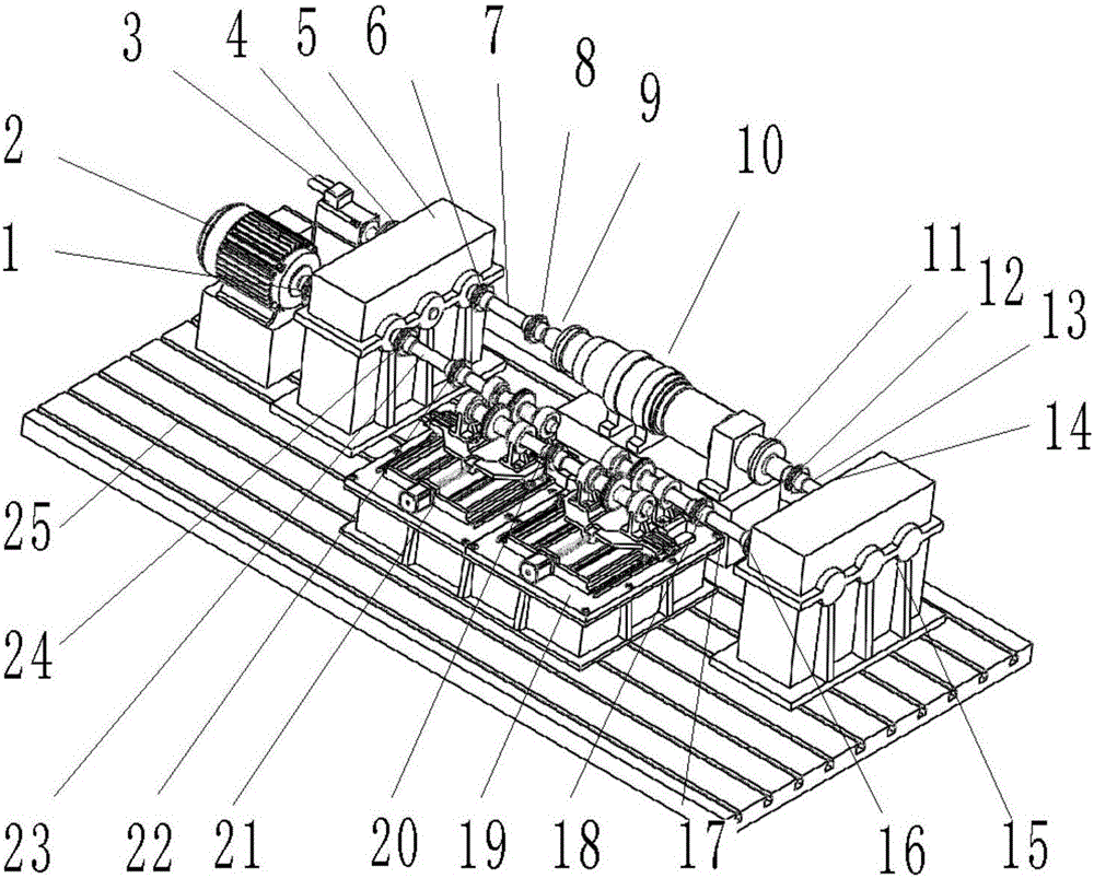
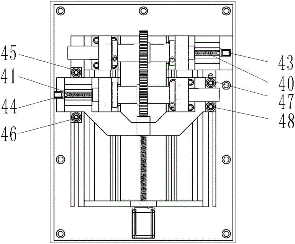
[0032] Such as figure 1 and 2As shown, the present invention comprises frequency conversion AC motor (2), servo motor (3), two closed cylindrical gear boxes (5, 15), hydraulic swing cylinder (10), main test bench (21), accompanying test bench (19), ten elastic couplings (1,6,8,12,14,16,18,20,22,24), four intermediate transmission shafts (7,13,17,23), two links flanges (9,11), a clutch (4). One side on the floor iron (25) is installed frequency conversion alternating current motor (2), starts from servomotor (3), installs first closed cylinder gear box (5), hydraulic swing cylinder (10), The second enclosed cylindrical gear box (15), the companion gear test stand (19), the main test gear test stand (21), and the variable frequency AC motor (2).

[0033] On the side of the floor iron, the output end of the servo motor (3) is connected with the second input end ...


PUM


Abstract

The invention discloses a high-power cylindrical gear comprehensive performance test bench with the stepless adjustable center distance. A drive motor is installed at one side of a terrace iron unit; a first closed cylindrical gear box, a first elastic coupling, a first intermediate shaft, a second elastic coupling, and a high-power hydraulic oscillating cylinder are installed clockwise; the output end of the oscillating cylinder is connected with a second closed cylindrical gear box by a connecting flange, a third elastic coupling, and a second intermediate shaft; the second closed cylindrical gear box is connected with an accompanying gear test bench by a fourth elastic coupling, a fifth elastic coupling, and a third intermediate shaft; the accompanying gear test bench and an active gear test bench are connected by a sixth elastic coupling; and the active gear test bench is provided with a seventh elastic coupling, a fourth intermediate shaft, and an eighth elastic coupling successively towards the direction of the first closed cylindrical gear box. The comprehensive performance test bench can be adjusted conveniently and mounted or dismounted rapidly. With a hydraulic expansion sleeve, repeated mounted or dismounted of a shafting at a bearing seat is avoided; and the requirement of long-term frequent testing can be met.

Description

technical field [0001] The invention discloses a high-power cylindrical gear comprehensive performance test bench, in particular to a precise cylindrical gear comprehensive performance test bench with infinitely adjustable center distance and rapid replacement. Background technique [0002] Cylindrical gears include spur gears, helical spur gears, spiral spur gears, etc. In actual production, gear is the main part of mechanical transmission, and its failure will directly affect the normal operation of the machine. In order to make the gear mechanism work reliably, it is necessary to measure the bending strength of the gear teeth, the contact strength of the tooth surface and the gluing bearing capacity, so as to analyze the mechanism of gear damage and provide a basis for the design of gear transmission. Such a complicated process only It can be carried out on the gear test bench. The test bench can comprehensively test: under different loads and speeds and different lubri...

Claims


Application Information

Patent Timeline
IPC IPC(8): G01M13/02
CPCG01M13/021
Inventor 吕浩亮吴鹏辉王喆滕国阳潘豪杰万博文周晓军
Owner ZHEJIANG UNIV
Learn More