
Combustion particle image acquisition device and method

An image acquisition device and particle technology, applied in the field of optical imaging, can solve the problems of indistinguishable flame front and particle shape, excessive light intensity between particles and flame, and indistinguishable particle and flame, so as to improve the success rate and accuracy, Effects with high image quality and easy operation

Inactive Publication Date: 2017-03-22
湖南七迪视觉科技有限公司
View PDF7 Cites 3 Cited by
  • Summary
  • Abstract
  • Description
  • Claims
  • Application Information

AI Technical Summary

Problems solved by technology

When a camera is used to continuously shoot metal particles such as Al, Mg, B, etc. in the combustion process, the image surface of the detector is saturated due to the excessive light intensity generated by the particles and the flame, and the resulting image is a large bright spot that cannot be distinguished Flame Front and Particle Morphology
In the above image acquisition methods, the excessive light intensity of particles and flames during the combustion process has become the bottleneck of this technology
Therefore, it is of great practical significance to explore an image acquisition method that solves the indistinguishability of particles and flames

Method used


Image

  • Combustion particle image acquisition device and method
  • Combustion particle image acquisition device and method

Examples


Embodiment Construction

[0015] In order to make the object, technical solution and advantages of the present invention clearer, the present invention will be further described in detail below in conjunction with the accompanying drawings and embodiments. It should be understood that the embodiments described below by referring to the figures are examples, and are only for explaining the present invention, and should not be construed as limiting the present invention.

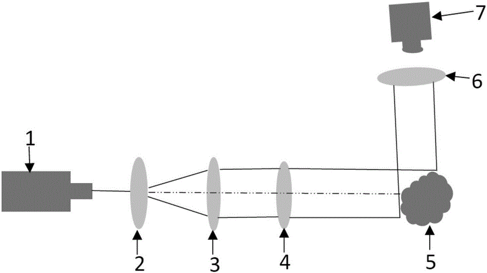
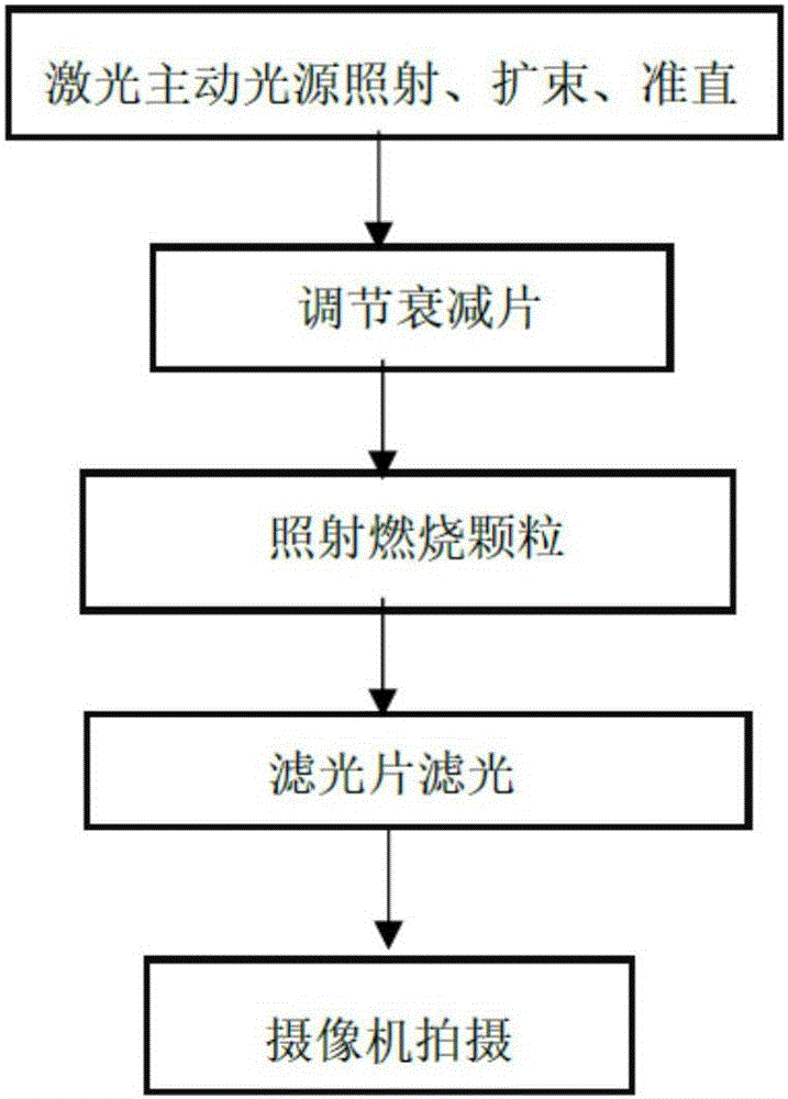
[0016] figure 1 It is a schematic diagram of the structure of a burning particle image acquisition device proposed by an embodiment of the present invention. The device includes a laser active light source 1, a beam expander lens 2, a collimating lens 3, an attenuation plate 4, a burning particle placement platform 5, an optical filter 6 and a camera 7.

[0017] Laser active light source 1, which provides a light source whose wavelength band does not intersect with the particle combustion emission light band 965nm-1931nm, and is used ...


PUM

PropertyMeasurementUnit
diameteraaaaaaaaaa

Abstract

The invention belongs to the field of optical imaging and particularly relates to a combustion particle image acquisition device and method, aiming at mainly solving the problem that a particle shape and a flame frontal surface cannot be distinguished in a combustion particle imaging process, and obtaining high-quality combustion particle and flame images. The device comprises a laser active light source, an expanded beam lens, a collimation lens, an attenuation sheet, a combustion particle placement platform, an optical filter and a camera. The laser active light source provided by the invention is used for illuminating, and the optical filter guarantees the passing of reflecting light of a wave band of the laser active light source and is used for an acquisition method of images photographed by the camera matched with the wave band of the laser active light source, so that a clear particle combustion image is obtained; the method is simple and easy to operate; the acquired image has high quality and less background noises; the difficulty that particles and flame form bright spots in a passive detection process is overcome; and in the obtained image, the particle shape and the flame frontal surface in the obtained image are clear and have a good distinction degree, and the success rate and accuracy of dividing the particles and flame can be improved.

Description

technical field [0001] The invention belongs to the field of optical imaging, and in particular relates to a burning particle image acquisition device and method, which focuses on solving the problem that the particle shape and flame front cannot be distinguished when burning particle imaging, and obtains high-quality burning particle and flame images. Background technique [0002] Monitoring the particle size variation of Al, Mg, B and other metal particles in the combustion process can be used to study the ignition and combustion mechanism of solid propellants such as solid rocket ramjet, water ramjet, and powder fuel ramjet. When a camera is used to continuously shoot metal particles such as Al, Mg, B, etc. in the combustion process, the image surface of the detector is saturated due to the excessive light intensity generated by the particles and the flame, and the resulting image is a large bright spot that cannot be distinguished Flame front and particle morphology. In...

Claims


Application Information

Patent Timeline
Patent Type & Authority Applications(China)
IPC IPC(8): G01N15/02
CPCG01N15/0227
Inventor 阎勇
Owner 湖南七迪视觉科技有限公司
Learn More