Novel precision shunt
A shunt, precision technology, applied in the direction of instruments, measuring devices, measuring electrical variables, etc., can solve the problems of difficult to break through the range, large temperature rise, large resistance, etc., achieve wide measurement range, improve measurement accuracy, and good heat dissipation Effect
- Summary
- Abstract
- Description
- Claims
- Application Information
AI Technical Summary
Problems solved by technology
Method used
Image

Examples
specific Embodiment approach
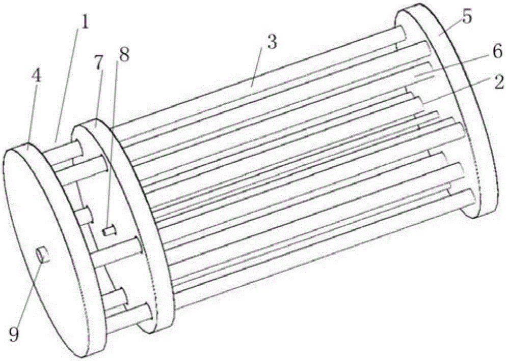
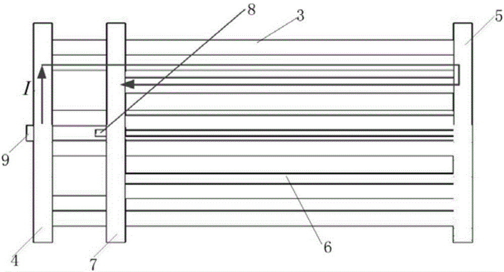
[0031] Taking the measurement of the pulse current source standard of 1kA as an example, the structural parameters of the shunt that can be used are: 8 pairs of cages inside and outside, the radius of the cage is 1mm, the length of the outer cage is 105mm, the length of the inner cage is 80mm, and the conductor material is constantan , and its nominal resistance is about 1.5mΩ.
[0032] In use, the current input and output can be connected to the first conductive plate 4 and the second conductive plate 5 of the shunt through a radio frequency level coaxial connector, and the voltage measurement can be performed by measuring the potential difference between the central wire 8 and the third conductive plate 7 Obtained, the voltage is about 1.5V.
PUM
 Abstract
Description
Claims
Application Information
 - Generate Ideas
- Intellectual Property
- Life Sciences
- Materials
- Tech Scout
- Unparalleled Data Quality
- Higher Quality Content
- 60% Fewer Hallucinations
Browse by: Latest US Patents, China's latest patents, Technical Efficacy Thesaurus, Application Domain, Technology Topic, Popular Technical Reports.
© 2025 PatSnap. All rights reserved.Legal|Privacy policy|Modern Slavery Act Transparency Statement|Sitemap|About US| Contact US: help@patsnap.com