
Self-test auxiliary device and self-test method for visual hardware of distribution terminal

A technology for power distribution terminals and auxiliary devices, applied in the electric power field, can solve problems such as unfavorable large-scale production and management, irregular test reports, and inability to achieve, and achieve the effects of saving external equipment, facilitating aging tests, and facilitating maintenance.

Active Publication Date: 2017-03-22
SHIJIAZHUANG KE ELECTRIC
View PDF12 Cites 7 Cited by
  • Summary
  • Abstract
  • Description
  • Claims
  • Application Information

AI Technical Summary

Problems solved by technology

[0003] There are many types of power distribution terminals (including feeder terminal FTU, station terminal DTU, and distribution transformer terminal TTU), and the automation functions are not completely the same. Manufacturers need to produce various types of terminals for debugging according to user needs , aging and inspection process, the whole process is completely dependent on the production of skilled workers and external equipment, in the manual stage, the test method is simple, the test report is not standardized, and it is greatly affected by factors such as manual skills and mental state, and human-introduced errors are not affected In this way, the traditional power distribution terminal test method is not only inefficient, but also not conducive to large-scale production and management, and cannot achieve consistency and comprehensive testing
[0004] In addition, the traditional power distribution terminal product aging test and hardware test are carried out separately, and there is no periodic real-time detection of hardware during the aging process and storage of detection data

Method used


Image

  • Self-test auxiliary device and self-test method for visual hardware of distribution terminal
  • Self-test auxiliary device and self-test method for visual hardware of distribution terminal
  • Self-test auxiliary device and self-test method for visual hardware of distribution terminal

Examples


Embodiment Construction

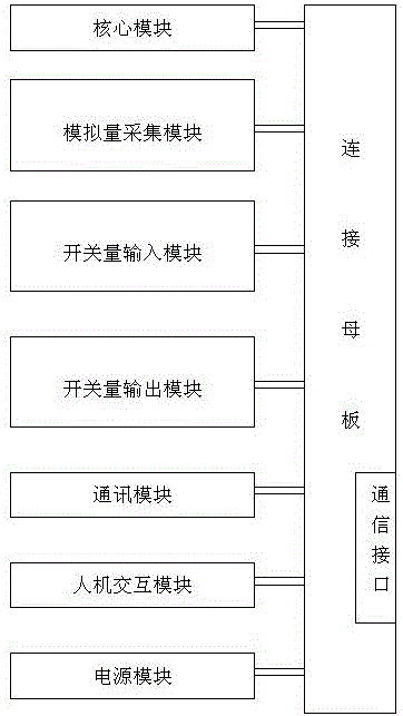
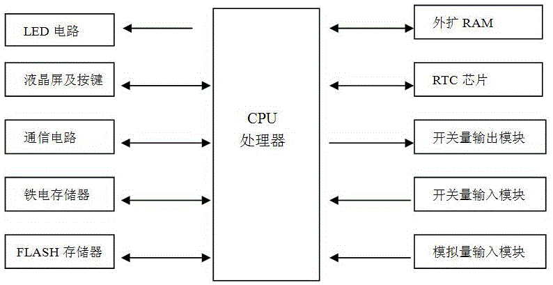
[0042] A visual hardware self-inspection auxiliary device for power distribution terminals, used to detect power distribution terminals, such as figure 2 As shown, the power distribution terminal includes a connecting motherboard and functional modules plugged into the connecting motherboard. The functional modules include an analog acquisition module, a digital input module, a digital output module, a human-computer interaction module, a communication module and a core module. , the core module is equipped with CPU, RTC chip and memory, and the human-computer interaction module includes a set of LED lights and a display screen. Each module is connected to the CPU through the connecting motherboard. The schematic diagram of the power distribution terminal is as follows: image 3 shown.

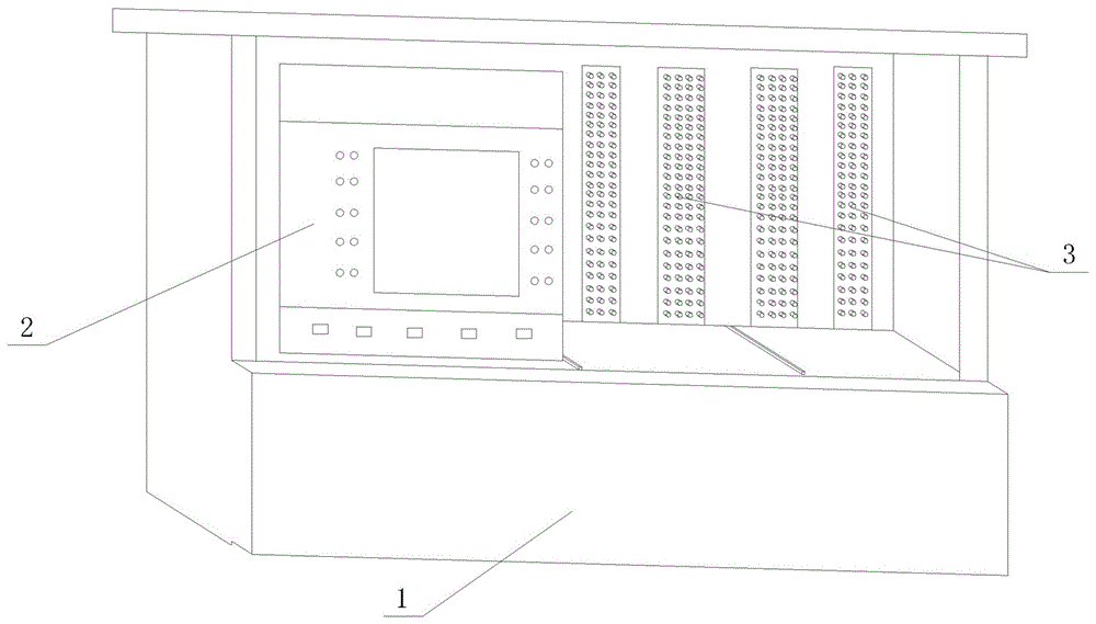
[0043] The auxiliary device includes a test cavity and a connector arranged in the housing 1, such as figure 1 As shown, the connector 3 is located at the back of the test chamber, the fron...


PUM


Abstract

A self-test auxiliary device and method for visual hardware of a distribution terminal belongs to the technical field of electrical power. The auxiliary device is used for carrying out test wiring of the distribution terminal. A self-test program module is used for automatically complete analog acquisition channel detection, on-off input and output consistency detection, and memory and clock detection for a distribution terminal to be tested. A liquid crystal screen or an LED lamp on the distribution terminal is used for indicating the detection process and the detection result. At the same time, an examination filed is formed and stored in a memory for production technical personnel to consult. For unqualified products, abnormal hardware can be rapidly found according to a self-test file. Periodic self-test of hardware is carried out in the product aging process, the hardware quality problem caused by hardware welding, assembly and the like in the aging process is recorded, automatic testing of distribution terminal hardware is achieved, the test efficiency and the terminal product quality are improved, and the phenomenon that test items are missed due to human factors is avoided.

Description

technical field [0001] The invention belongs to the technical field of electric power, and relates to a data acquisition and control terminal of power distribution equipment in a power grid, in particular to auxiliary equipment and a detection method for power distribution terminal detection. Background technique [0002] In recent years, with the continuous improvement of the degree of power automation, as the front-end components of power distribution automation, power distribution terminals cooperate with power distribution switches, switch cabinets, distribution transformers and other equipment to become one of the indispensable components to realize power distribution automation. The demand is constantly increasing. The power distribution terminal is equipped with a connecting motherboard, and functional modules are set on the connecting motherboard. [0003] There are many types of power distribution terminals (including feeder terminal FTU, station terminal DTU, and ...

Claims


Application Information

Patent Timeline
IPC IPC(8): G01R31/00
CPCG01R31/00
Inventor 陈贺安志国屈国旺陈洪雨吴纳磊胡金路李英春贾海旭王雷克辛海斌刘海涛常生强袁玉宝朱雅通王强
Owner SHIJIAZHUANG KE ELECTRIC
Learn More