Optical path configuration eliminating cold image of infrared continuous zooming optical system

An optical system and optical path technology, applied in optics, optical components, instruments, etc., can solve the problems of reducing the dynamic range of the system and losing the sensitivity of the system, and achieve the effect of reducing the limitation, expanding the dynamic range and eliminating the influence.

Active Publication Date: 2017-03-22
LUOYANG INST OF ELECTRO OPTICAL EQUIP OF AVIC
View PDF6 Cites 3 Cited by
  • Summary
  • Abstract
  • Description
  • Claims
  • Application Information

AI Technical Summary

Problems solved by technology

[0005] At present, the method of electric correction is usually adopted at home and abroad to improve or weaken the intensity of narcissus, and compensate

Method used


Image

  • Optical path configuration eliminating cold image of infrared continuous zooming optical system
  • Optical path configuration eliminating cold image of infrared continuous zooming optical system
  • Optical path configuration eliminating cold image of infrared continuous zooming optical system

Examples


Embodiment Construction

[0034] Embodiments of the present invention are described in detail below, and the embodiments are exemplary and intended to explain the present invention, but should not be construed as limiting the present invention.

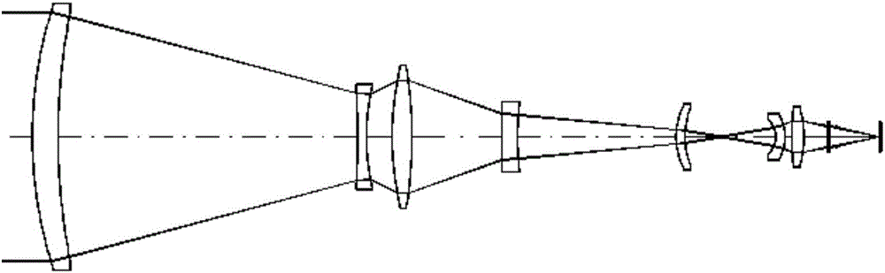
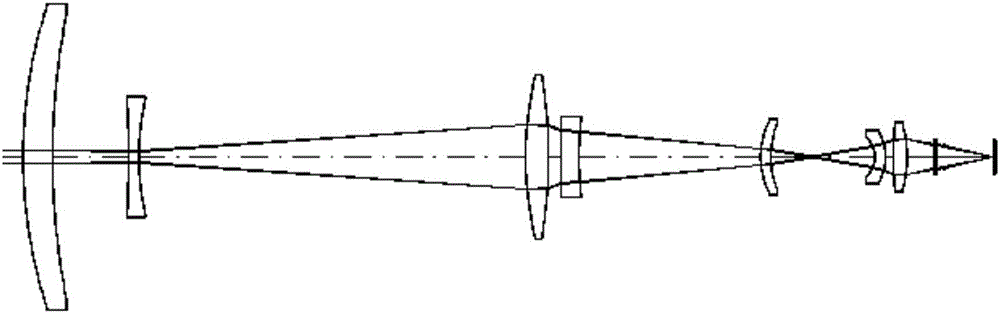
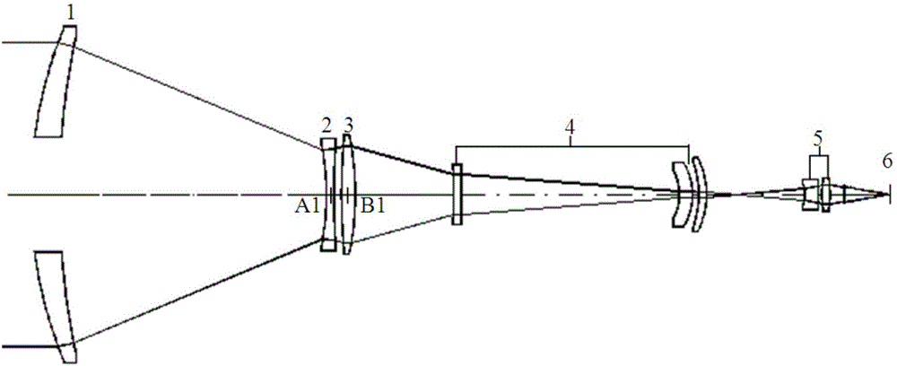
[0035] The purpose of the present invention is to provide an optical path configuration that eliminates the cold image of the infrared continuous zoom optical system, eliminates the influence of the cold image on the optical system, and enables each optical field of view to have high imaging quality and effect at the same time.

[0036] The optical system adopts the segmental continuous zooming method of the long focus section and the short focus section, and adopts the configuration of the front group hollow objective lens to separate the optical path of the long focus section and the short focus section of the optical system. While realizing the infrared large zoom ratio continuous zoom optical system, The narcissus of the short focal length of the optical sy...


PUM

PropertyMeasurementUnit
Radiusaaaaaaaaaa
Center thicknessaaaaaaaaaa
Radiusaaaaaaaaaa

Abstract

The invention provides an optical path configuration eliminating a cold image of an infrared continuous zooming optical system. A front group of hollow object lenses, a zooming lens group, a compensation lens group, a fixed lens group, a convergent lens group and a detector form a long focal length segment of the continuous zooming optical system; the zooming lens group, the compensation lens group, the fixed lens group, the convergent lens group and the detector form a short local length segment of the continuous zooming optical system; when the zooming lens group and the compensation lens group are placed in the positions A1B1, an optical path of the long focal length end of the long focal length segment is formed; when the zooming lens group and the compensation lens group are placed in the positions A2B2, an optical path of the short focal length end of the long focal length segment is formed; when the zooming lens group and the compensation lens group are placed in the positions A3B3, an optical path of the long focal length end of the short focal length segment is formed; and when the zooming lens group and the compensation lens group are placed in the positions A4B4, an optical path of the short focal length end of the short focal length segment is formed. According to the invention, the long focal length segment and the short focal length segment are used for continuous zooming, configuration of the front group of hollow object lenses separates optical paths of the long focal length segment from those of the short focal length segment, the infrared high-zooming-ratio continuous zooming optical system is realized, cold reflection of the short focal length segment of the optical system is inhibited effectively, images are kept clear in the whole zooming process, and high image quality is obtained.

Description

technical field [0001] The invention relates to the technical field of optical path design, in particular to an optical path configuration for eliminating cold images of an infrared continuous zoom optical system. Background technique [0002] The infrared continuous zoom thermal imager is an imaging system whose focal length can be changed continuously, while the position of the image plane remains stable and the image quality remains good during the zooming process. In order to obtain images of different sizes on the image plane of a fixed-focus infrared camera, the distance between the target object and the lens must be changed or a lens with a different focal length must be replaced. The infrared continuous zoom thermal imager can continuously change the focal length of the system. Therefore, it can obtain target images of continuously changing sizes on the image plane, which is very beneficial for photoelectric detection, reconnaissance, and tracking. It is widely used...

Claims


Application Information

Patent Timeline
IPC IPC(8): G02B15/14
CPCG02B15/14
Inventor 刘红霞张良吴晓鸣梁兴龙
Owner LUOYANG INST OF ELECTRO OPTICAL EQUIP OF AVIC
Why Eureka
Try Eureka