

3D projection system based on digital micromirror device
A digital micromirror and projection system technology, applied in the field of projection, can solve the problems of inconvenient portability or placement, large size of the projector, etc., and achieve the effect of making up for the loss of brightness, small size, high brightness and contrast ratio
- Summary
- Abstract
- Description
- Claims
- Application Information
AI Technical Summary
Problems solved by technology
Method used
Image

Examples
Embodiment Construction
[0011] In order to make the purpose, technical solution and advantages of the present invention clearer, the specific implementation manners of the present invention will be further described in detail below.
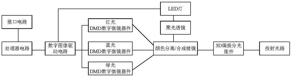
[0012] Including processor circuit, digital image driving circuit, digital micromirror module and interface circuit, said digital micromirror module includes DMD digital micromirror device, LED light, condensing lens, color separation / Synthetic prism, projection lens group, the light emitted by the LED lamp is separated into red light, blue light, and green light through the color separation / separation optical path of the synthetic prism, and then respectively projected to the DMD digital micromirror device of the corresponding color, DMD digital micromirror After being reflected by the device, it passes through the synthetic light path of the color separation / synthesis prism, and then projects through the projection lens group; the signal output end of the interface ci...
PUM
 Abstract
Description
Claims
Application Information