
Method and device for positioning aircraft

A positioning method and aircraft technology, applied in the computer field, can solve problems such as large amount of calculation, poor GPS positioning accuracy, and the positioning method cannot achieve precise positioning, and achieve the effect of accurate calculation

Inactive Publication Date: 2017-03-22
TENCENT TECH (SHENZHEN) CO LTD
View PDF3 Cites 39 Cited by
  • Summary
  • Abstract
  • Description
  • Claims
  • Application Information

AI Technical Summary

Problems solved by technology

For the existing method 1, the GPS equipment in the aircraft needs to be positioned outdoors, avoiding high-rise buildings, woods, tunnels, etc., and the accuracy of GPS positioning is relatively poor, and the general error is between 5 and 10 meters. In addition, when the GPS starts the aircraft, it needs to wait for the search satellite signal, so that the aircraft cannot take off quickly
For the existing method 2, the optical flow camera uses the optical flow method to detect moving objects. In practical applications, due to reasons such as occlusion, multiple light sources, transparency, and noise, the gray-scale conservation assumption of the basic equation of the optical flow field The conditions cannot be met. The optical flow camera positioning method can only be used to locate the aircraft indoors. At the same time, most of the optical flow calculation methods are quite complicated, with a huge amount of calculation, and cannot meet the real-time requirements, so they are not suitable for precision and real-time performance. aircraft with high requirements
For the existing method 3, the disadvantage of inertial sensor positioning is that there will be accumulated errors, which are related to the accuracy of the sensor, which will reduce the positioning accuracy of the aircraft
[0004] In summary, the existing positioning methods for aircraft in the prior art cannot achieve accurate positioning

Method used


Image

  • Method and device for positioning aircraft
  • Method and device for positioning aircraft
  • Method and device for positioning aircraft

Examples


Embodiment Construction

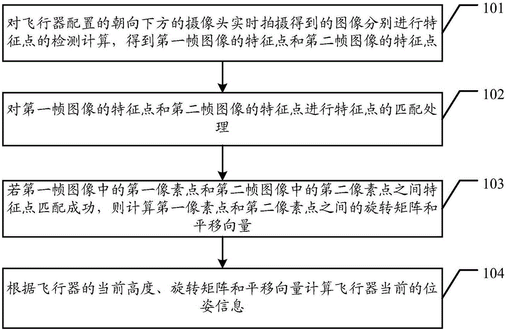
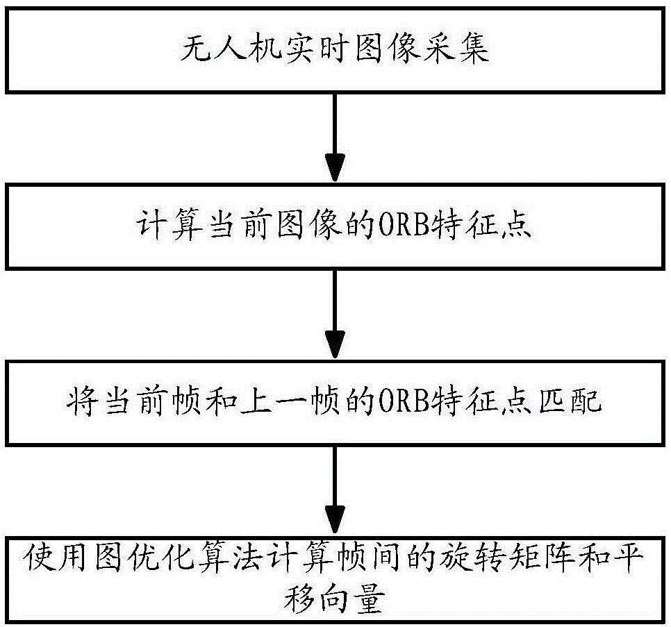
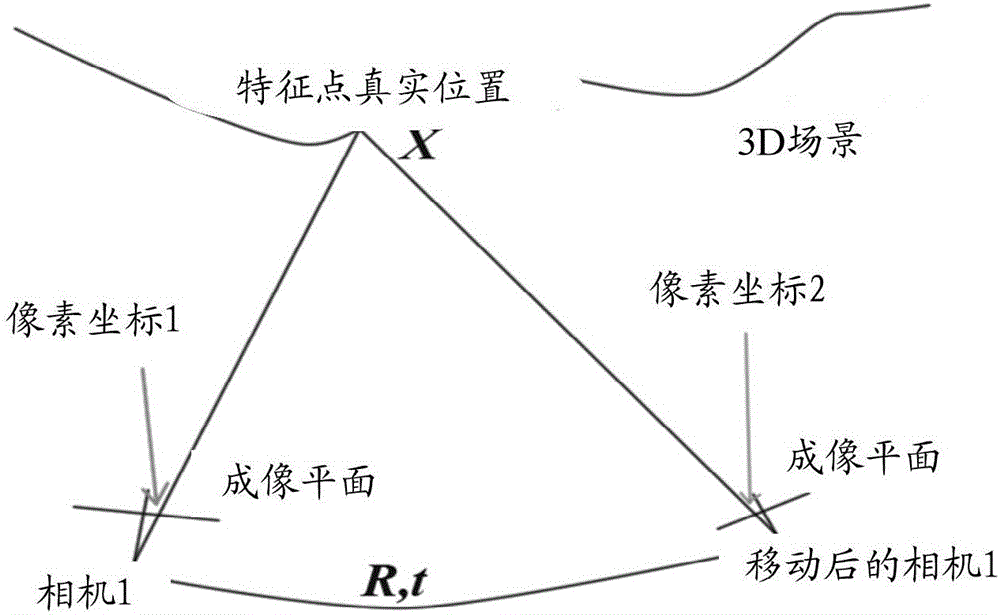
[0027] Embodiments of the present invention provide an aircraft positioning method and device, which are used to reduce the positioning error of the aircraft and improve the positioning accuracy of the aircraft.

[0028] In order to make the purpose, features and advantages of the present invention more obvious and understandable, the technical solutions in the embodiments of the present invention will be clearly and completely described below in conjunction with the accompanying drawings in the embodiments of the present invention. Obviously, the following The described embodiments are only some, not all, embodiments of the present invention. All other embodiments obtained by those skilled in the art based on the embodiments of the present invention belong to the protection scope of the present invention.

[0029] The terms "comprising" and "having" in the description and claims of the present invention and the above drawings, as well as any variations thereof, are intended t...


PUM


Abstract

The invention discloses a method and a device for positioning an aircraft, which are used for reducing a positioning error of the aircraft and improving the positioning accuracy of the aircraft. The method provided by the embodiment of the invention for positioning the aircraft comprises the steps of respectively performing feature point detection and calculation on images photographed in real time by a downward camera configured by the aircraft so as to acquire feature points of a first frame image and feature points of a second frame image, wherein the first frame image and the second frame image are images acquired by respectively photographing two adjacent frames; performing feature point matching processing on the feature points of the first frame image and the feature points of the second frame image; if features points between a first pixel point in the first frame image and a second pixel point in the second frame image are successfully matched, calculating a rotation matrix and a translation vector between the first pixel point and the second pixel point; and calculation current position and attitude information of the aircraft according to the current height of the aircraft, the rotation matrix and the translation vector.

Description

technical field [0001] The invention relates to the field of computer technology, in particular to a positioning method and device for an aircraft. Background technique [0002] Unmanned aircraft is referred to as aircraft for short. Aircraft has many applications in national economy and military affairs. At present, aircraft has been widely used in aerial photography, power inspection, environmental monitoring, forest fire prevention, disaster inspection, terrorism and lifesaving, military reconnaissance, In the field of battlefield assessment and other fields, the aircraft is an unmanned aircraft controlled by radio remote control equipment and its own program control device. There is no cockpit on board, but it is equipped with autopilot, program control device, information collection device and other equipment. The remote control station personnel track, locate, remote control, telemetry and digital transmission through radar and other equipment. [0003] In the prior a...

Claims


Application Information

Patent Timeline
Patent Type & Authority Applications(China)
IPC IPC(8): G06K9/32G06K9/62
CPCG06V10/245G06V10/751
Inventor 黄盈
Owner TENCENT TECH (SHENZHEN) CO LTD
Features
  • Generate Ideas
  • Intellectual Property
  • Life Sciences
  • Materials
  • Tech Scout
  • Unparalleled Data Quality
  • Higher Quality Content
  • 60% Fewer Hallucinations
Learn More