Apparatus and method for generating glow discharge striations

A glow discharge and stripe technology, applied in the direction of solid cathode components, cold cathode tubes, etc., can solve the problems of irregular distribution of electron density and electron temperature, no selectivity, complex structure, etc., and achieve rich and stable active particles Good, simple structure effect

Inactive Publication Date: 2017-03-22
SHANXI UNIV
View PDF6 Cites 4 Cited by
  • Summary
  • Abstract
  • Description
  • Claims
  • Application Information

AI Technical Summary

Problems solved by technology

[0004] The purpose of the present invention is to overcome the shortcomings of the prior art, provide a device and method for generating glow discharge stripes, and solve the existing problems of existing devices for

Method used


Image

  • Apparatus and method for generating glow discharge striations

Examples


Embodiment 1

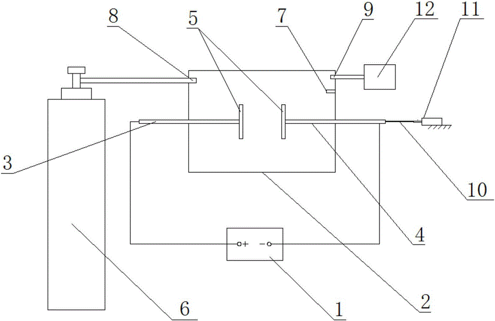
[0019] Such as figure 1 As shown, a device for generating glow discharge stripes in this embodiment includes a DC power supply 1, an anode 3, a cathode 4 and a workbench, wherein: a glow discharge chamber 2 is also included, and the glow discharge chamber 2 One side wall is provided with an argon gas inlet 8, and the other side wall of the glow discharge chamber 2 is provided with a vacuum port 9 and a vacuum degree tester 7, and the glow discharge chamber 2 is connected with the vacuum port 9 The vacuum pumping device 12 is connected, and the glow discharge chamber 2 is connected with the argon gas storage device 6 through the argon gas inlet 8;

[0020] One end of the anode 3 and the cathode 4 are arranged in the glow discharge chamber 2 through the two side walls of the glow discharge chamber 2, and the ends of the anode 3 and the cathode 4 are respectively provided with plate electrodes 5 parallel to each other; The other end of the anode 3 is connected to the positive po...

Embodiment 2

[0030] A method for producing glow discharge stripes with the glow discharge stripe device in embodiment 1, comprising the following steps:

[0031] 1) Install and connect various instruments and equipment, and check their tightness and insulation;

[0032] 2) The vacuum pumping device 12 draws air outwards through the vacuum port 9, and observes the vacuum degree tester 7 at the same time until the air pressure in the glow discharge chamber 2 is maintained at 8kpa, and the pumping is stopped;

[0033] 3) Fill the glow discharge chamber 2 with argon gas with a concentration of 99.999% through the argon gas inlet 8, and observe the vacuum degree tester 7 at the same time, so that the air pressure in the glow discharge chamber 2 is maintained at 9kpa, and the air intake is stopped. ;

[0034] 4) Turn on the DC power supply 1, and then gradually increase the voltage, so that the gas breaks down and a glow discharge plasma is formed between the plate electrodes 5;

[0035] 5) Ad...

Embodiment 3

[0037] A method for producing glow discharge stripes with the glow discharge stripe device in embodiment 1, comprising the following steps:

[0038] 1) Install and connect various instruments and equipment, and check their tightness and insulation;

[0039] 2) The vacuum pumping device 12 draws air outwards through the vacuum port 9, and observes the vacuum tester 7 at the same time until the air pressure in the glow discharge chamber 2 is maintained at 8.1kpa, and the pumping is stopped;

[0040] 3) Fill the glow discharge chamber 2 with argon gas with a concentration of 99.999% through the argon gas inlet 8, and observe the vacuum degree tester 7 at the same time, so that the air pressure in the glow discharge chamber 2 is maintained at 9.1kpa, and stop charging. gas;

[0041] 4) Turn on the DC power supply 1, and then gradually increase the voltage, so that the gas breaks down and a glow discharge plasma is formed between the plate electrodes 5;

[0042] 5) Adjust the vol...


PUM


Abstract

The invention relates to an apparatus and a method for generating glow discharge striations, belongs to the technical field of glow discharge, and mainly aims to solve the technical problems of complex structure, poor stability, irregular distribution of electronic density and electronic temperature, and no selectivity in an application process existing in the prior art. According to a technical scheme, the apparatus for generating the glow discharge striations comprises a direct current power supply, a positive electrode, a negative electrode and a workbench, and also comprises a glow discharge cavity, wherein an argon inlet is formed in one side wall of the glow discharge cavity while a vacuumizing port and a vacuum degree tester are arranged on the other side wall of the glow discharge cavity; one ends of the positive electrode and the negative electrode pass through the two side walls of the glow discharge cavity to be arranged in the glow discharge cavity; plate-shaped electrodes which are in parallel are arranged at the ends at one ends of the positive electrode and the negative electrode respectively; the other end of the positive electrode is connected with the positive electrode of the direct current power supply; the other end of the negative electrode is connected with the negative electrode of the direct current power supply and an insulating rod; and the insulating rod is connected with a micrometer.

Description

technical field [0001] The invention belongs to the technical field of glow discharge, in particular to a device and method for generating glow discharge stripes. Background technique [0002] Glow discharge streak plasma is a low-temperature plasma under relatively harsh conditions. In addition to the basic characteristics of low-temperature plasma, its biggest feature is that the discharge stratification leads to the stratification of active particles. By developing this discharge layering technology and controlling the concentration of active particles in each layer, it can play a huge role in the application process. [0003] However, because it is usually difficult to achieve a uniform glow discharge under atmospheric pressure, filamentary discharge is very likely to occur in the axial direction, which affects the uniformity of the discharge, and even transitions to an arc discharge. There is an irregular distribution of electron density and electron temperature. There...

Claims


Application Information

Patent Timeline
IPC IPC(8): H01J17/06H01J17/40
CPCH01J17/06H01J17/40
Inventor 朱海龙董有尔
Owner SHANXI UNIV
Why Eureka
Try Eureka