
Lens detection method and device

A lens detection and lens technology, applied in the field of image processing, can solve problems such as inability to integrate and form a unified standard, prone to misjudgment and missed detection, high personnel ability requirements, etc., achieve good denoising effect, and the method is simple and easy, The effect of simple image processing methods

Active Publication Date: 2017-03-22
NINGBO SUNNY AUTOMOTIVE OPTECH
View PDF9 Cites 18 Cited by
  • Summary
  • Abstract
  • Description
  • Claims
  • Application Information

AI Technical Summary

Problems solved by technology

However, at present, the judgment of whether there is stray light in the image is mainly based on the human eye, which leads to the following problems:
[0005] 1. The determination of stray light has high requirements on the ability of personnel, and the personnel who are not experienced enough are prone to misjudgment and missed detection when judging stray light; if in order to avoid the problem of missed detection and misjudgment, it is necessary to Multiple stray light tests are used in the process, not only the process is more complicated, but also the labor cost is high and the efficiency is low;
[0006] 2. When manually judging stray light, each person's judgment is highly subjective, and the judging criteria and results are based on real pictures, which cannot be integrated to form a unified standard
Although this patent discloses a detection method for stray light, this detection method requires the use of attenuation sheets and complex calculation formulas, which is difficult to implement and has relatively low processing efficiency
[0009] Aiming at the problems of high misjudgment rate, easy missed detection, low efficiency and difficult implementation in the stray light determination scheme in the related technology, no effective solution has been proposed so far

Method used


Image

  • Lens detection method and device
  • Lens detection method and device
  • Lens detection method and device

Examples


Embodiment Construction

[0082] The description of this illustrative embodiment should be taken in conjunction with the accompanying drawings, which should be considered a part of this complete specification. In the drawings, the shapes or thicknesses of the embodiments may be exaggerated and marked for simplification or convenience. Furthermore, parts of each structure in the drawings will be described separately. It should be noted that elements not shown in the drawings or described in words are forms known to those of ordinary skill in the art.

[0083] The descriptions of the embodiments here, any references to directions and orientations are just for convenience of description, and should not be construed as any limitation to the protection scope of the present invention. The following descriptions of the preferred embodiments involve combinations of features, which may exist independently or in combination, and the present invention is not particularly limited to the preferred embodiments. The...


PUM


Abstract

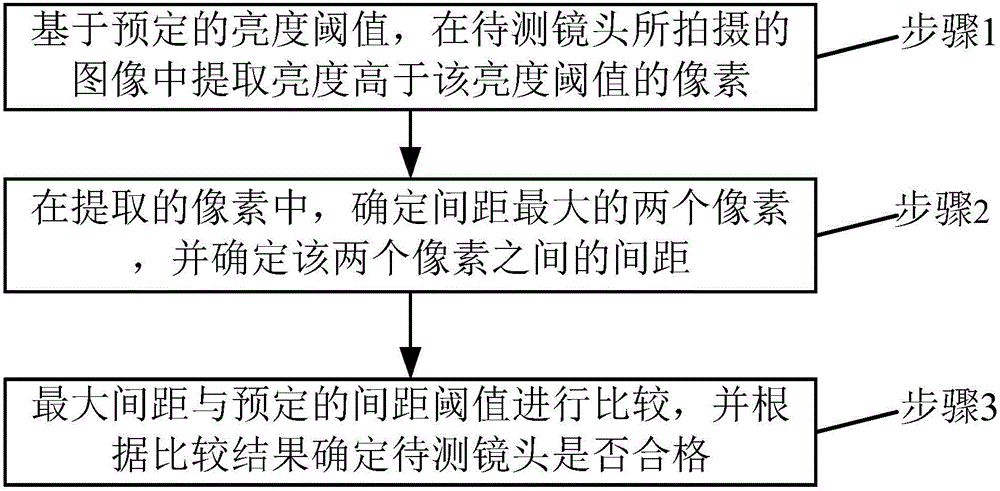
The invention discloses a lens detection method and device. The method comprises the following steps: step 1, extracting pixels with brightness higher than a brightness threshold in an image shot by a to-be-measured lens based on the predetermined brightness threshold; step 2, in the extracted pixels, determining two pixels having the largest distance, and determining the distance between the two pixels; and step 3, comparing the largest distance with a predetermined distance threshold, and determining whether the to-be-measured lens is qualified according to a comparison result. By adoption of the lens detection method and device disclosed by the invention, the detection can be performed in a unified and objective manner to avoid the problems of high misjudgment rate and easy detection leakage caused by manual judgment, so that the detection accuracy is relatively high; and moreover, since the image processing method adopted by the lens detection method and device disclosed by the invention is relatively simple, it is easy to implement, the processing efficiency is relatively high, the detection time can be effectively shortened, which is conducive to improving the production efficiency.

Description

technical field [0001] The present invention relates to the field of image processing, and in particular, to a lens detection method and device. Background technique [0002] When the camera lens forms a real image of an object, in addition to the imaging light, there are other non-imaging rays that diffuse on the image surface of the optical system. These non-imaging rays are called stray light. Stray light usually comes from radiation sources outside the system, internal radiation sources, and non-imaging light energy from scattering surfaces, such as reflected light from various refractive surfaces such as optical components and structural parts, reflected light from the inner wall of the instrument, diffuse reflection of the lens itself, or The reflection of the lens barrel may cause stray light. In addition, the problem of stray light may also occur due to dust contamination of optical parts, damage to optical components, glue leakage, mismatched apertures, and large di...

Claims


Application Information

Patent Timeline
IPC IPC(8): H04N17/00
CPCH04N17/002
Inventor 范立权
Owner NINGBO SUNNY AUTOMOTIVE OPTECH
Learn More