Washing machine environment-friendly water-saving working method and washing machine thereof

A working method and technology of a washing machine, applied in the field of washing machines, can solve problems such as poor design of the shape of the chute, achieve fewer sealing links, prevent secondary pollution, and have good reliability

Active Publication Date: 2017-03-29
NINGGUO JULONG IND
View PDF6 Cites 2 Cited by
  • Summary
  • Abstract
  • Description
  • Claims
  • Application Information

AI Technical Summary

Problems solved by technology

[0004] Existing patent documents (application number 20120076912.7 and application number 201510171392.2 ) mentioned a drainage control valve, in which a self-locking mechanism is set in the valve body to realize the drainage function of the inner bucket, but the self-locking mechanism needs to design the shape of the chute to realize the positioning, the shape of the chute is not well designed, and the motor action is used. Guidance and gravity of the trough, precise motor energization time

Method used


Image

  • Washing machine environment-friendly water-saving working method and washing machine thereof
  • Washing machine environment-friendly water-saving working method and washing machine thereof
  • Washing machine environment-friendly water-saving working method and washing machine thereof

Examples


Embodiment 1

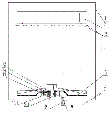
[0035] Combined graph 1 As shown, this embodiment provides an environment-friendly water-saving washing machine, and the washing machine includes an outer tub 1 and inner barrel 2 , the outer barrel of the 1 There is a drain at the bottom of the bucket 7 , the inner barrel of the 2 It is an integral water storage barrel, and the inner barrel 2 The uppermost end is provided with a balance ring, and the lower end of the balance ring is provided with a 2 A ring of water throwing holes on the central axis 3 , inner barrel 2 Concentrically mounted on the outer barrel 1 inside, the inner barrel of the 2 A deceleration clutch is arranged below, and the power output shaft above the deceleration clutch and the inner barrel 2 Bottom connection, and for the inner barrel 2 transmission, and at the same time decelerate the power take-off shaft above the clutch and the upper shaft sleeve 12 Clearance fit, inner barrel flange 6 Concentrically mou...

Embodiment 2

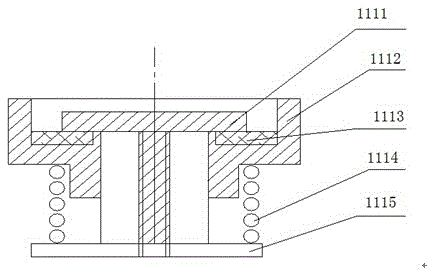
[0051] as shown in the picture 3 As shown, others are the same as in the embodiment 1 , the difference is that the annular push plate 101 with upper sleeve 12 There is a concentric gap fit between them, which can move along the axial direction of the upper sleeve, and the annular push plate 101 Located on inner drum flange 6 Bottom; ring push plate 101 The structure is changed to the structure shown in the figure, and the second guide post is omitted 21 . The advantage of this embodiment is that the second guide post is omitted 21 , thus simplifying the device without affecting the normal operation of the washing machine and ensuring the original functions.

Embodiment 3

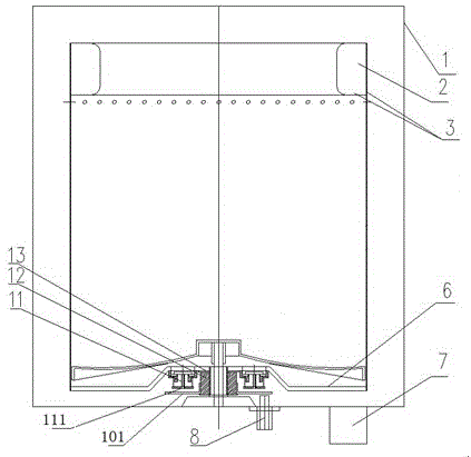
[0053] as shown in the picture 4 As shown, others are the same as in the embodiment 1 , the difference is: the manipulator is an electromagnet 8 with fork 16 , the shift fork 16 with mounted on outer barrel 1 Fork fulcrum on inner bottom 15 active connection, and the fork 16 with electromagnet 8 The corresponding position is provided with a material that can be magnetically adsorbed, and the fulcrum of the shift fork 15 with electromagnet 8 Distributed on both sides of the vertical rotation central axis of the washing machine. When the controller is working, set it on the outer tub of the washing machine 1 Electromagnet on the outside 8 Start working under the instructions of the computer board program, through the electromagnet 8 pair set on the fork 16 Pull the fork down due to the adsorption of the magnetically adsorbable material on the 16 at one end, at the same time at the fulcrum of the fork 15 Under the action of the shift fork 16 The...


PUM


Abstract

The invention relates to the technical field of washing machines, and in particular relates to a washing machine environment-friendly water-saving working method and a washing machine thereof; by adoption of the technical scheme provided by the invention, the defects that an existing washing machine wastes water and has secondary pollution are overcome; the environment-friendly water-saving washing machine provided by the invention comprises an inner barrel and an outer barrel, wherein the inner barrel is concentrically arranged in the outer barrel, and is characterized in that the inner barrel is an integral water storage barrel, the bottom of the inner barrel is connected with an inner barrel flange, the inner barrel flange is mounted on an upper shaft sleeve of a speed reduction clutch, the inner barrel flange is provided with a normally-closed check valve, the lower part of the normally-closed check valve is provided with an annular push plate for controlling the normally-closed check valve to move up and down, the annular push plate is arranged at the bottom of the inner barrel flange through a guide post in a manner of moving up and down, and is controlled to move up and down by an electromagnet arranged on the bottom of the outer barrel; the outer barrel contains no water, water is saved by 20 percent or above, and the secondary pollution to clothes is avoided; sealing links are less, the implementation is easy and the reliability is good.

Description

technical field [0001] The invention relates to the field of washing machines, in particular to an environment-friendly water-saving working method for washing machines and the washing machine . Background technique [0002] Fully automatic washing machines are composed of an inner tub and an outer tub set together. The bottom of the outer tub is connected with a deceleration clutch. The pulsator shaft and the dehydration shaft of the deceleration clutch are respectively connected with the pulsator and the inner tub. The inner tub is provided with lateral drainage holes. Therefore, the water between the inner bucket and the outer bucket is connected, that is, the liquid level is the same, and the water between the inner bucket and the outer bucket has no effect on the clothes. During the entire washing process, nearly 20% The water is wasted, and the most important point is that the water in this space also has the problem of secondary pollution of clothes, because ther...

Claims


Application Information

Patent Timeline
Patent Type & Authority Applications(China)
IPC IPC(8): D06F35/00D06F39/08
CPCD06F35/005D06F39/083Y02B40/00
Inventor 刘军
Owner NINGGUO JULONG IND
Why Eureka
Try Eureka