
Railroad bridge separating type double-box steel main girder structure without independent tuyere

A separate, steel girder technology, applied to bridges, bridge parts, bridge materials, etc., can solve the problems of difficulty in construction quality and construction precision control, low material utilization rate, inconvenient transportation, etc., to ensure construction Accuracy and construction quality are beneficial to road transportation and the effect of saving steel consumption

Inactive Publication Date: 2017-03-29
CHINA RAILWAY SIYUAN SURVEY & DESIGN GRP
View PDF10 Cites 9 Cited by
  • Summary
  • Abstract
  • Description
  • Claims
  • Application Information

AI Technical Summary

Problems solved by technology

In addition, the entire section of the steel box girder is large in size and inconvenient to transport. Generally, the plate units are prefabricated in the factory and assembled and welded on the construction site, resulting in a large amount of welding on site, and it is difficult to control the construction quality and construction accuracy.
The safety and comfort of train driving require that the railway bridge must have a certain local lateral stiffness, and if the long-span railway cable-stayed bridge adopts an integral steel box girder section, the section needs to be widened, resulting in low material utilization and poor economic efficiency

Method used


Image

  • Railroad bridge separating type double-box steel main girder structure without independent tuyere
  • Railroad bridge separating type double-box steel main girder structure without independent tuyere
  • Railroad bridge separating type double-box steel main girder structure without independent tuyere

Examples


Embodiment Construction

[0026] pass below Figure 1 to Figure 6 And the way of enumerating some optional embodiments of the present invention, the technical solution of the present invention (including the preferred technical solution) is described in further detail, and any technical feature and any technical solution in this embodiment do not limit the protection scope of the present invention .

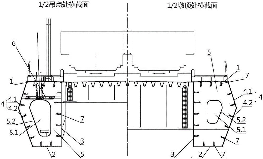
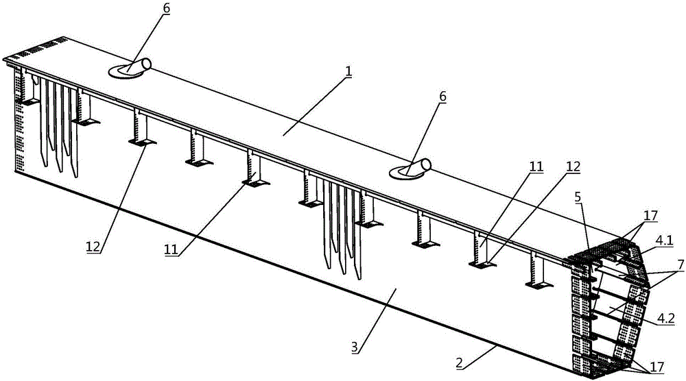
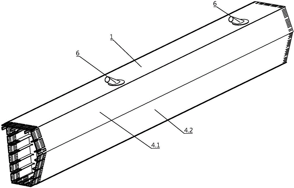
[0027] Such as Figure 1 to Figure 6 As shown, the separated double-box steel girder structure of the railway bridge without independent air nozzles designed by the present invention comprises a bridge deck system, and a separated side box girder is arranged on both sides of the bridge deck system in the transverse bridge direction; One side of the side box girder is connected with the bridge deck by bolts, and the other side is provided with a diversion structure; Split side box girder sections are joined by bolts.

[0028] Such as figure 1 and figure 2 As shown, the separated side box girder secti...


PUM


Abstract

The invention discloses a railroad bridge separating type double-box steel main girder structure without an independent tuyere. The railroad bridge separating type double-box steel main girder structure comprises a bridge deck system, and separating time side box girders are arranged on the two sides of the bridge deck system in the cross bridge direction. One side of each separating type side box girder is connected to the bridge deck system in a stud welded manner. Each separating type side box girder comprises a plurality of separating type side box girder segments arranged in the bridge direction, and the separating type side box girder segments which are adjacent in the bridge direction are spliced through bolts. The designed main girder structure is definite in stress, and the number of local stability problems is relatively small. Compared with an integrated steel box girder, the railroad bridge separating type double-box steel main girder structure has the beneficial effects that the structural size is reduced, the structure can be prefabricated in a factory, on-site joint welding is avoided, and the construction precision and the construction quality are guaranteed; compared with a steel longeron, the railroad bridge separating type double-box steel main girder structure has the beneficial effects that the trival splicing work between joints is reduced, the steel amount is reduced, the structure is simple and concise in outer surface, and the maintenance amount is low; and the railroad bridge separating type double-box steel main girder structure is good in wind-resistant performance for medium and small span bridges.

Description

technical field [0001] The invention belongs to the technical field of bridges, and in particular relates to a main girder structure suitable for medium and small-span railway bridges. Background technique [0002] The main girder structure of existing railway cable-stayed bridges adopts steel truss girders or integral steel box girders. Although the technology of steel truss girders and integral steel box girders is relatively mature, there are still the following imperfections: [0003] (1) For steel truss girders, the cross-section of the main girder is relatively high, and it is difficult to adopt a concrete main girder structure. Therefore, generally the whole bridge adopts a steel structure main girder, which consumes a large amount of steel and is economical; secondly, due to the joint structure and many spliced ​​plates As well as factors such as the large slenderness ratio of the rods and the stability control design, the material utilization rate of the steel truss...

Claims


Application Information

Patent Timeline
IPC IPC(8): E01D2/04E01D19/00E01D101/30
CPCE01D2/04E01D19/00E01D2101/30
Inventor 刘振标曾敏罗世东傅萌萌王伟民赵涛
Owner CHINA RAILWAY SIYUAN SURVEY & DESIGN GRP
Learn More