
Terminal module used for cable conduction detection

A terminal module and conduction detection technology, which is applied in the direction of fault detection according to conductor type, aircraft component testing, fault location, etc., to achieve the effect of halving the number of test nodes, improving test efficiency, and improving test efficiency

Inactive Publication Date: 2017-03-29
CHINA AVIATION OPTICAL-ELECTRICAL TECH CO LTD
View PDF3 Cites 4 Cited by
  • Summary
  • Abstract
  • Description
  • Claims
  • Application Information

AI Technical Summary

Problems solved by technology

[0003] The purpose of the present invention is to convert the traditional two-end test into a single-end test, solve the problem of using a large number of process transfer cables in the automatic detection of the cable of the whole machine, and optimize the cable detection method

Method used


Image

  • Terminal module used for cable conduction detection
  • Terminal module used for cable conduction detection
  • Terminal module used for cable conduction detection

Examples


Embodiment Construction

[0021] Determine the type of connector part 1 of the terminal module according to the type of the connector at the other end of the cable under test, and calculate the parameters of the diode 7 and resistor 6 according to the conduction principle requirements of the test instrument.

[0022] According to the number of cores of the tested cable, determine the number of diodes and resistance components. When the number of cores is odd, the connection diagram is as follows: image 3 As shown, when the number of cores is even, the connection diagram is as follows Figure 4 shown.

[0023] In order to ensure the stability of the connection between the electronic components and the contacts, a heat-conducting adhesive layer 2 is poured at the soldering point, which not only ensures the connector, but also meets the heat dissipation requirements of the electronic components. , to ensure insulation performance; a metal shield 5 is added outside the terminal module to protect internal...


PUM


Abstract

The invention belongs to the field of passive testing and specifically relates to a terminal module used for cable conduction detection. In a conventional cable test system, a detected cable is connected with a test device after being switched through a test cable, and the two ends of the detected cable need to be switched by use of the test cable; and an adaptor cable is quite clumsy and disordered to use. According to the terminal module, an opening end of a metal protective cover is provided with a connector part, the metal protective cover internally comprises an electronic component, the electronic component comprises multiple unidirectional conduction circuits composed of electronic diodes and resistors, and two end points of each unidirectional conduction circuit are connected with pins corresponding to the connector part; and when a cable is detected, the terminal module is connected with the cable, and by applying test signals to the pins corresponding to the other end of the cable, conduction performance of the cable is determined. A test system is simplified, and at the same time, the performance requirement for a master control unit of the test system is reduced.

Description

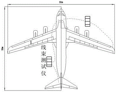
technical field [0001] The invention belongs to the field of passive testing, and in particular relates to a terminal module for cable continuity detection. Background technique [0002] Existing cable testing system connects the cable under test to the test equipment after switching the test cable, such as figure 1 As shown, both ends of the tested cable need to be transferred with the test cable; when the cable is installed and laid, the transfer cable is very cumbersome and messy to use. Taking a certain type of aircraft as an example, such as figure 2 As shown, to test the cable assembly between the cockpit flight control computer and the tail elevator, the distance between the two is more than 50m, and the transfer cable is used for testing. The total length of the cables at both ends must be greater than 50m. At this time, the length and weight of the transfer cable will increase. Seriously affect the test efficiency. Contents of the invention [0003] The purpos...

Claims


Application Information

Patent Timeline
IPC IPC(8): G01R31/08B64F5/60
CPCG01R31/083
Inventor 陈学永李雪冬刘宁吕云朋胡培根陈建超蔡艳召
Owner CHINA AVIATION OPTICAL-ELECTRICAL TECH CO LTD
Learn More